A Background on Power Over Ethernet (PoE, PoE+ & Hi-PoE)

PSEs and PDs - what is the difference

Similar to the way the wire pair that carries your POTS (Plain Old Telephone System) telephone signal into your house provides sufficient power for the headset, dial, and ringer systems for your telephone, PoE delivers DC power over standard Ethernet cabling (CAT3 and better). Since 2003, the PoE (IEEE 802.3af) and PoE+ (IEEE 802.3at) standards have been conveniently used to power and connect network devices that required voltage up to 30 watts. Using these standards, organizations commonly deployed equipment in locations that are difficult or too costly to have separate AC power installed -- such as ceilings, walls, and kiosks.

However, for PoE above 30 watts vendors began developing proprietary, non-interoperable (UPoE, 4PPoE, PoE++, UltraPoE, 4 Pair PoE, etc) implementations that made deployments of multiple vendor product solutions difficult. With the ratification of the IEEE 802.3bt High Power PoE (Hi-PoE) standard in 2018, which can deliver up to 100W per port, there is now alignment between Hi-PoE vendors and no more compatibility issues between their products. The Hi-PoE standard is backward compatible with the existing PoE and PoE+ standards and helps to expand the adoption of standard PoE products and increase the demand for PoE powered products. The differences between IEEE PoE standards are:

IEEE PoE Specifications for Cat5e @100m
Standard / Type 802.3af
Type 1
802.3at
Type 2
802.3bt
Type 3
802.3bt
Type 4
Name / Year PoE / 2003 PoE+ / 2009 Hi-PoE / 2018 Hi-PoE / 2018
PSE Input Voltage (Min) 44V/50V 50V 52V
Supported PD Class 1 2 3 4 5 6 7 8
PSE Output Power to Single-Signature PD 4W 6.7W 14W 30W 45W 60W 75W 90W - 100W
Single-Signature PD Input Power (Min) 3.84W 6.49W 13W 25.5W 40W 51W 62W 71.3W
PSE Output Power to Dual-Signature PD (per pairset) 4W 6.7W 14W 30W 45W -- -- --
Dual-Signature PD Input Power (pairset / total) 3.84W /
7.68W
6.49W /
12.98W
13W /
26W
25.5W /
51W
35.6W /
71.2W
-- -- --
Ethernet Pairs 2-Pair 2-Pair or
4-Pair
4-Pair

To support the power demands of the IoT market, PoE technology, with the introduction of the IEEE 802.3bt standard, can support up to 100W of power at the Power Source Equipment (PSE). Some High Power applications likely to take advantage of the Hi-PoE standard are:

  1. Smart City and Building infrastructure (i.e. LED lighting)
  2. Retail POS systems, VoIP phones, and digital signage
  3. High-performance network devices (i.e. Wireless Access Points (WAPs) supporting IEEE 802.11ac & 802.11ax, IP turrets, TVs, and Monitors)
  4. High definition pan-tilt-zoom security cameras with heaters for harsh environments
  5. Healthcare & Industrial Networks
  6. Retail (i.e. POS, Vending Machines)

PoE, sometimes referred to as “inline power”, significantly reduces the number of wires that must be strung to install a network. Additional advantages include greater flexibility for the location of installed equipment, less downtime, lower wiring costs, and lower power costs.

PSEs and PDs - what is the difference

There are two main types of devices used in a PoE environment -- the Power Source Equipment (PSE) and the Powered Device (PD). The PSE provides the power and the PD accepts the power. A PoE PSE provides a maximum of 15.4 watts of power at 48vDC. A PoE+ PSE provides a maximum of 30 watts of power at 48vDC. A Hi-PoE PSE provides a maximum of 100 watts of power. Four pair cable is required by the IEEE standards. CAT5 cable has four twisted pairs, however, only two of the pairs are used for data. The specification allows for either the spare pairs or the data pairs to be used to carry the power.

How does PoE work?

Power is “injected“ into the cabling at the wire-closet side. This can be done through “end-span“ LAN/WAN switches which incorporate power supply circuitry.  Alternatively, if you don't want to replace existing LAN switches, or only want to power some segments, “mid-span“ power patch panels or injectors can be connected in-between the switch and the Powered Device (PD). The end PDs have to support PoE. Many PoE switches are also capable of power management so that connected PoE devices can be power cycled. This is ideal for remote management applications where IT equipment, such as servers and routers, need to be power cycled to recover.

PoE Power Sources

When a PoE Powered Device (PD) is turned on, the PD informs the Ethernet end-span or mid-span switch through an information exchange that it can receive power through the Ethernet cable. A fully complaint IEEE PoE PD can accept power over the data lines or unused pins on the Ethernet interface.   In this area network administrators need to be cautious because some PD’s claiming compliance with the IEEE PoE standards are restricted to using mid-span power sources utilizing only the unused pairs.  Mid-span injectors do not always verify the end device they are powering is a PD and could, therefore, cause damage to non-PD devices.

To protect the PD’s from input current rushes that may occur during power-up, the PD must have inrush current protection. The PD with this protection begins with a low current draw stage to protect the power sourcing equipment (PSE) and then switches to a high current stage allowing the PD to draw its required power up a maximum of 100 watts.

Single-signature and Dual-signature PDs

802.3bt introduced two new PD topologies -- single-signature and dual-signature. Single-signature PDs share the same detection signature, classification signature, and maintain power signature between both pair sets. This is usually used with single load applications. Dual-signature PDs have independent detection signatures, classification signatures, and maintain power signatures on each pair set. This is ideal for multi-load applications, like surveillance cameras with a heater.  Today, deployments of dual-signature PDs allow for 51W to be delivered at the PD. However, newer PD deployments are likely to use single-signature PDs to save on overall product cost and take advantage of the higher 71W power availability. It will be important to determine if the PSE supports single-signature PDs, dual-signature PDs, or both when planning a deployment.  A PSE that supports both will not need to be replaced as PDs are updated.

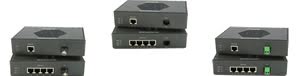
Going beyond 100 meters

For remote devices that need to receive power and data, but are beyond the100 meter reach of copper, network managers have several options.  They could add a remote data closet, use LAN extenders that convert Ethernet to DSL, use UTP to coax converters, install wireless technology or, they could utilize the benefits of fiber optic cable to extend the distance of the network. 

Fiber extends network distances up to 100 miles (160 km) per link without the long-distance data deterioration associated with copper cabling. LAN extenders can extend network distances up to 6 miles (10 km), but anything beyond 328 ft will have significantly slower data speeds.  Instead of 100 Mbps, your data rate will slow down to as little as 2.3 Mbps. Furthermore, fiber cabling provides security benefits. It does not generate electromagnetic emission and is very difficult to tap. And, since it is not susceptible to electrical interference, or data loss due to temperature or atmospheric conditions, Fiber is extremely reliable.

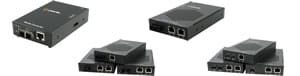
Fiber can be run from an existing data closet to an area with access to power.  A PoE Media Converter can be powered by either AC or DC power. The media converter is attached to the power supply and the fiber cable.  Copper (UTP or STP cable) Ethernet can be extended another 100 meters to the PD.  The PoE Media Converter is converting the data from fiber to copper, adding power, and transmitting it to the PD.

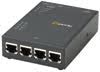
When you need to extend Ethernet services beyond the general IEEE 802.3 limits of 328ft / 100m, and new fiber cabling is cost prohibitive, Ethernet Extenders are the perfect solution. Ethernet Extenders transparently extend 10/100/1000 Ethernet connections across copper wiring. Use single twisted pair (CAT5/6/7), coax, or any existing copper wiring previously used in alarm circuits, E1/T1 circuits, RS-232, RS-422, RS-485, CCTV, and CATV applications. A PoE Ethernet Extender can operate as a PD or a PSE.

In summary, the benefits of PoE technology are:

  • Only one set of wires to bring to your Ethernet appliance - simplifies installation and saves space.
  • There is no need to pay for an expensive electrician, or delay your installation to meet the electrician's schedule - saves time and money.
  • The appliance can be easily moved to wherever you can lay a LAN cable - minimal disruption to the workplace.
  • Safer - no mains voltages anywhere.
  • A UPS can guarantee power to appliances even during a mains power failure.
  • Appliances can be shut down or reset remotely - no need for a reset button or power switch.

Perle PoE Products

Hi!

Have a Question? Chat with a live Product Specialist!

Have a Question?

We can provide more information about our products or arrange for a price quotation.


email-icon Send an Email
contactus-icon Send an Email callus-icon Call Us
×

Send us an Email