

Live Chat Now
→
Send an Email
→
Call Us
→
Error!
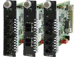
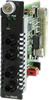
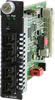
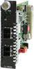
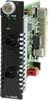
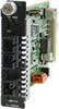
Installed in a high density Perle Media Converter Chassis, Perle's feature rich CM-100MM Fast Ethernet Fiber to Fiber Managed Media Converter Module enables transparent fiber extension of 100Base-FX multimode fiber to 100Base-FX multimode or 100Base-LX/EX/ZX/BX single mode fiber.
Perle's advanced features make the end to end fiber link completely transparent. This allows for more efficient troubleshooting and less on-site maintenance. When used with a Media Converter Management Module in the chassis, configuration and monitoring of the fiber ports can be performed. In addition, a lifetime warranty and free worldwide technical support make Perle's CM-100MM Fast Ethernet Fiber to Fiber Managed Media Converter Modules the smart choice for IT professionals.
For those environments requiring a medium to large-scale deployment of media converters, a centralized platform that simplifies the configuration, administration, monitoring, and troubleshooting of this gear is recommended. PerleVIEW Device Management software is a multi-user, Windows server-based application that delivers this level of Enterprise-grade solution.
Whether you need to extend multimode to multimode or multimode to single mode, Perle has an extensive range of CM-100MM Fast Ethernet Fiber to Fiber Managed Media Converter Modules to meet your fiber conversion requirement.
| Configuration Mode selection | Select whether the module is to use the on-board DIP switches or enable the management module in the chassis to manage |
| Module Information |
|
| Module DIP switch settings | View hardware DIP switch settings |
| Port Control | Enable or disable individual fiber ports on the module |
| Fiber Port Status |
|
| Module Control |
|
| Backup and Restore | Provides fast and easy module replacement. Management module will always save a copy of the media converter configuration and will restore this configuration automatically to the media module when it is detected in the slot. |
| |
| Far-End Fault (FEF) |
|
| Pause (IEEE 802.3xy) | Pause signaling is an IEEE feature that temporarily suspends data transmission between two devices in the event that one of the devices becomes overwhelmed. The media converter is transparent to Pause frames. |
| Signal Regeneration | Signal Regeneration maintains signal integrity and allows for maximum fiber to fiber connections without degradation. |
| Cascading | Media Converters can be cascaded. Two or more Media Converters can be chained in a link to achieve even greater distances. |
| VLAN | The Media Converter is transparent to VLAN tagged packets. |
| Remote Loopback | The Media Converter can perform a loopback on each 100Base-X fiber interface. |
Specifications
HTSUS Number:
8517.62.0020
UNSPSC Code:
43201553
ECCN:
5A991


Indicators
Power / TST
This green LED is turned on when power is applied to the media converter. Otherwise it is off. The LED will blink slowly when in Loopback test mode.
Fiber link 1 / Receive activity (LK1)
This green LED is operational only when power is applied. The LED is on when the 100Base-X link is on and flashes with a 50% duty cycle when data is received.
Fiber link 2 on / Receive activity (LK2)
This green LED is operational only when power is applied. The LED is on when the 100Base-X link is on and flashes with a 50% duty cycle when data is received.
Switches: On-Board (If Auto/Switch strap is set to Switch)
Link Pass Through
Far-End Fault (FEF)
Remote Loopback #1
Remote Loopback #2
Configuration Mode (Strap)
Auto (default) enable management module to overwrite hardware switch settings
Switch - Use onboard DIP switches
Cables
Fiber Optic Cable
Packet Transmission Characteristics
Bit Error Rate (BER)
<10 -12
Environmental Specifications
Operating Temperature
0°C to 50°C (32°F to 122°F)
Storage Temperature
minimum range of -25°C to 70°C (-13 F to 158 F)
Operating Humidity
5% to 90% non-condensing
Storage Humidity
5% to 95% non-condensing
Operating Altitude
Up to 3,048 meters (10,000 feet)
Heat Output (BTU/HR)
11.9
Maximum Power Consumption (watts)
3.5
MTBF (Hours)
484,202 Hours
Calculation model based on MIL-HDBK-217-FN2 @ 30°C
Mechanical - Hot Swapping Card
Edge Connecter
32 pin DIN 41612 / IEC 60603-2 Type B/2 Male. Fist make, last break for ground and power
Card insertion and removal
Captive thumb screws enable fast insertion and removal. Can be further tighten with a screwdriver.
Product Weight
Weight
0.15 kg, 0.33 lbs
Packaging
Shipping Weight
0.33 kg, 0.73 lbs
Shipping Dimensions
203 x 38 x 152 mm, 8 x 1.5 x 6 inches
Regulatory Approvals
Emissions
Immunity
CISPR 35 / EN 55035
Safety
Laser Safety
Select a Model to obtain a Part Number - CM-100MM Fast Ethernet Fiber to Fiber Managed Media Converter Module
| Model | Port | Connector | Type | Transmit (dBm) | Receive (dBm) | Power Budget (dBm) | Wavelength (nm) | Fiber Type | Operating Distance | ||
|---|---|---|---|---|---|---|---|---|---|---|---|
Min | Max | Min | Max | ||||||||
| CM-100MM-M2ST2 | Port 1 | Dual ST | 100BASE-FX | -20.0 | -12.0 | -31.0 | -14.0 | 11.0* | 1310 | MMF | 2 km (1.2 mi) |
| Port 2 | Dual ST | 100BASE-FX | -20.0 | -12.0 | -31.0 | -14.0 | 11.0* | 1310 | MMF | 2 km (1.2 mi) | |
| CM-100MM-M2SC2 | Port 1 | Dual SC | 100BASE-FX | -20.0 | -12.0 | -31.0 | -14.0 | 11.0* | 1310 | MMF | 2 km (1.2 mi) |
| Port 2 | Dual SC | 100BASE-FX | -20.0 | -12.0 | -31.0 | -14.0 | 11.0* | 1310 | MMF | 2 km (1.2 mi) | |
| CM-100MM-M2LC2 | Port 1 | Dual LC | 100BASE-FX | -20.0 | -12.0 | -30.0 | -14.0 | 10.0* | 1310 | MMF | 2 km (1.2 mi) |
| Port 2 | Dual LC | 100BASE-FX | -20.0 | -12.0 | -30.0 | -14.0 | 10.0* | 1310 | MMF | 2 km (1.2 mi) | |
| CM-100MM-S2ST20 | Port 1 | Dual ST | 100BASE-FX | -20.0 | -12.0 | -31.0 | -14.0 | 11.0* | 1310 | MMF | 2 km (1.2 mi) |
| Port 2 | Dual ST | 100BASE-LX | -18.0 | -7.0 | -32.0 | -3.0 | 14.0 | 1310 | SMF | 20 km (12.4 mi) | |
| CM-100MM-S2SC20 | Port 1 | Dual SC | 100BASE-FX | -20.0 | -12.0 | -31.0 | -14.0 | 11.0* | 1310 | MMF | 2 km (1.2 mi) |
| Port 2 | Dual SC | 100BASE-LX | -18.0 | -7.0 | -32.0 | -3.0 | 14.0 | 1310 | SMF | 20 km (12.4 mi) | |
| CM-100MM-S2LC20 | Port 1 | Dual LC | 100BASE-FX | -20.0 | -12.0 | -30.0 | -14.0 | 10.0* | 1310 | MMF | 2 km (1.2 mi) |
| Port 2 | Dual LC | 100BASE-LX | -15.0 | 0.0 | -34.0 | -5.0 | 19.0 | 1310 | SMF | 20 km (12.4 mi) | |
| CM-100MM-S2ST40 | Port 1 | Dual ST | 100BASE-FX | -20.0 | -12.0 | -31.0 | -14.0 | 11.0* | 1310 | MMF | 2 km (1.2 mi) |
| Port 2 | Dual ST | 100BASE-EX | -5.0 | 0.0 | -34.0 | -3.0 | 29.0 | 1310 | SMF | 40 km (25 mi) | |
| CM-100MM-S2SC40 | Port 1 | Dual SC | 100BASE-FX | -20.0 | -12.0 | -31.0 | -14.0 | 11.0* | 1310 | MMF | 2 km (1.2 mi) |
| Port 2 | Dual SC | 100BASE-EX | -5.0 | 0.0 | -34.0 | -3.0 | 29.0 | 1310 | SMF | 40 km (25 mi) | |
| CM-100MM-S2LC40 | Port 1 | Dual LC | 100BASE-FX | -20.0 | -12.0 | -30.0 | -14.0 | 10.0* | 1310 | MMF | 2 km (1.2 mi) |
| Port 2 | Dual LC | 100BASE-EX | -5.0 | 0.0 | -34.0 | -3.0 | 29.0 | 1310 | SMF | 40 km (25 mi) | |
| CM-100MM-S2ST80 | Port 1 | Dual ST | 100BASE-FX | -20.0 | -12.0 | -31.0 | -14.0 | 11.0* | 1310 | MMF | 2 km (1.2 mi) |
| Port 2 | Dual ST | 100BASE-ZX | -5.0 | 0.0 | -34.0 | -3.0 | 29.0 | 1550 | SMF | 80 km (50 mi) | |
| CM-100MM-S2SC80 | Port 1 | Dual SC | 100BASE-FX | -20.0 | -12.0 | -31.0 | -14.0 | 11.0* | 1310 | MMF | 2 km (1.2 mi) |
| Port 2 | Dual SC | 100BASE-ZX | -5.0 | 0.0 | -34.0 | -3.0 | 29.0 | 1550 | SMF | 80 km (50 mi) | |
| CM-100MM-S2LC80 | Port 1 | Dual LC | 100BASE-FX | -20.0 | -12.0 | -30.0 | -14.0 | 10.0* | 1310 | MMF | 2 km (1.2 mi) |
| Port 2 | Dual LC | 100BASE-ZX | -5.0 | 0.0 | -34.0 | -3.0 | 29.0 | 1550 | SMF | 80 km (50 mi) | |
| CM-100MM-S2ST120 | Port 1 | Dual ST | 100BASE-FX | -20.0 | -12.0 | -31.0 | -14.0 | 11.0* | 1310 | MMF | 2 km (1.2 mi) |
| Port 2 | Dual ST | 100BASE-ZX | 0.0 | 5.0 | -35.0 | -3.0 | 35.0 | 1550 | SMF | 120 km (75 mi) | |
| CM-100MM-S2SC120 | Port 1 | Dual SC | 100BASE-FX | -20.0 | -12.0 | -31.0 | -14.0 | 11.0* | 1310 | MMF | 2 km (1.2 mi) |
| Port 2 | Dual SC | 100BASE-ZX | 0.0 | 5.0 | -35.0 | -3.0 | 35.0 | 1550 | SMF | 120 km (75 mi) | |
| CM-100MM-S2LC120 | Port 1 | Dual LC | 100BASE-FX | -20.0 | -12.0 | -30.0 | -14.0 | 10.0* | 1310 | MMF | 2 km (1.2 mi) |
| Port 2 | Dual LC | 100BASE-ZX | 0.0 | 5.0 | -34.0 | -3.0 | 34.0 | 1550 | SMF | 120 km (75 mi) | |
Single Fiber Models (Recommended use in pairs)
| Model | Port | Connector | Type | Transmit (dBm) | Receive (dBm) | Power Budget (dBm) | Wavelength (nm) | Fiber Type | Operating Distance | ||
|---|---|---|---|---|---|---|---|---|---|---|---|
Min | Max | Min | Max | ||||||||
| CM-100MM-S1ST20U | Port 1 | Dual ST | 100BASE-FX | -20.0 | -12.0 | -31.0 | -14.0 | 11.0* | 1310 | MMF | 2 km (1.2 mi) |
| Port 2 | Single ST | 100BASE-BX | -14.0 | -8.0 | -32.0 | -3.0 | 18.0 | 1310/1550 | SMF | 20 km (12.4 mi) | |
| CM-100MM-S1ST20D | Port 1 | Dual ST | 100BASE-FX | -20.0 | -12.0 | -31.0 | -14.0 | 11.0* | 1310 | MMF | 2 km (1.2 mi) |
| Port 2 | Single ST | 100BASE-BX | -14.0 | -8.0 | -32.0 | -3.0 | 18.0 | 1550/1310 | SMF | 20 km (12.4 mi) | |
| CM-100MM-S1SC20U | Port 1 | Dual SC | 100BASE-FX | -20.0 | -12.0 | -31.0 | -14.0 | 11.0* | 1310 | MMF | 2 km (1.2 mi) |
| Port 2 | Single SC | 100BASE-BX | -14.0 | -8.0 | -32.0 | -3.0 | 18.0 | 1310/1550 | SMF | 20 km (12.4 mi) | |
| CM-100MM-S1SC20D | Port 1 | Dual SC | 100BASE-FX | -20.0 | -12.0 | -31.0 | -14.0 | 11.0* | 1310 | MMF | 2 km (1.2 mi) |
| Port 2 | Single SC | 100BASE-BX | -14.0 | -8.0 | -32.0 | -3.0 | 18.0 | 1550/1310 | SMF | 20 km (12.4 mi) | |
| CM-100MM-S1SC40U | Port 1 | Dual SC | 100BASE-FX | -20.0 | -12.0 | -31.0 | -14.0 | 11.0* | 1310 | MMF | 2 km (1.2 mi) |
| Port 2 | Single SC | 100BASE-BX | -8.0 | -3.0 | -33.0 | -3.0 | 25.0 | 1310/1550 | SMF | 40 km (25 mi) | |
| CM-100MM-S1SC40D | Port 1 | Dual SC | 100BASE-FX | -20.0 | -12.0 | -31.0 | -14.0 | 11.0* | 1310 | MMF | 2 km (1.2 mi) |
| Port 2 | Single SC | 100BASE-BX | -8.0 | -3.0 | -33.0 | -3.0 | 25.0 | 1550/1310 | SMF | 40 km (25 mi) | |
The minimum fiber cable distance for all converters listed is 2 meters.
*Based on use with 62.5/125 micron multimode fiber.
High Density Fiber Distribution from Fiber Switch Equipment at Corporate Headquarters
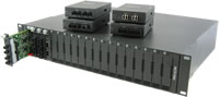
In this enterprise campus application, up to 18 Perle CM-100MM Multimode to Single mode Media Converters are installed in the MCR1900 Media Converter Chassis. The 19th slot in the chassis is filled the MCR-MGT Management Module. All media converts in the chassis are managed by SNMP, Telnet or an internet browser interface. A remote fiber enabled Ethernet switch is connected directly to the central MCR1900 Chassis. Another S-100MM Fiber to Fiber Media Converter is connected to a remote office switch. In all cases, multimode or single-mode fiber can be used. Fiber links can be extended up to 120km using single-mode fiber.
Managed Ethernet over Fiber Links
Manage your multimode to single mode or multimode to multimode link with an MCR200 chassis housing a media converter and management module. Ideal for use in managed networks with low density fiber applications, this Managed Media Converter is connected across a fiber link to a remote media converter. The copper or fiber link on the managed standalone unit can provide vital information and status to network management tools such as SNMP.
Fast Ethernet Multimode Switch to Multimode Switch
Extend the network distance between two Multimode Fiber Switches
Two Fiber to Fiber Media Converters can extend the distance between Fiber Switches across a fiber link up to 120km in length.
Single Mode / Single Fiber
When Single Strand fiber is used, a pair of Single Fiber Media Converters is needed for the fiber to fiber conversion. Perle Single Fiber Media Converters are also referred to as “Up/Down” models. For example the CM-100MM-S1SC20U (“Up”) and CM-100MM-S1SC20D (“Down”), shown below, must be used in pairs. An “Up” must be matched with a “Down” peer to deal with transmit and receive frequencies separately.
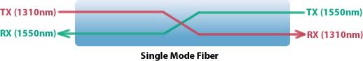
CM-100MM-S1SC20UCM-100MM-S1SC20D
The majority of installations for single mode fiber media converters are of the “dual connector” or “dual fiber” type where one fiber connection is used for transmit, the other for receive. These are physically “crossed” to match up the Transmit/Receive links.
However, to reduce costs, or where there are limits on available fiber, WDM technology may be utilized. WDM uses separate transmit and receive frequencies to communicate on a single fiber strand. WDM technology relies on the fact that optical fibers can carry many wavelengths of light simultaneously without interaction between each wavelength. Thus, a single fiber can carry many separate wavelength signals or channels simultaneously.
So remember, if Single Strand fiber is used, you will need an “Up” Media Converter on one side and a “Down” Media Converter on the other for fiber to fiber conversion.
Perle offers a wide variety of Single Fiber (“Up/Down”) Media Converters to connect 10BaseT, Fast Ethernet and Gigabit to single fiber. Whether you need Managed or Unmanaged, Standalone or Modular Chassis Based, 20km or 120km, Perle has the right model to meet your fiber conversion requirement.
Filter your options to find the right hardware for your application
Viewing 21 of 21 products
Click on a part number for ordering information
Product Image
Product Description
Part No.
CM-100MM-M2ST2 - Fast Ethernet Fiber to Fiber Media Converter Managed Module, 100Base-FX 1310nm multimode (ST) [2 km/1.2 miles] to 100Base-FX 1310nm multimode (ST) [2 km/1.2 miles]. Managed or unmanaged operation
CM-100MM-M2SC2 - Fast Ethernet Fiber to Fiber Media Converter Managed Module, 100Base-FX 1310nm multimode (SC) [2 km/1.2 miles] to 100Base-FX 1310nm multimode (SC) [2 km/1.2 miles]. Managed or unmanaged operation
CM-100MM-M2LC2 - Fast Ethernet Fiber to Fiber Media Converter Managed Module, 100Base-FX 1310nm multimode (LC) [2 km/1.2 miles] to 100Base-FX 1310nm multimode (LC) [2 km/1.2 miles]. Managed or unmanaged operation
CM-100MM-S2ST20 - Fast Ethernet Fiber to Fiber Media Converter Managed Module, 100Base-FX 1310nm multimode (ST) [2 km/1.2 miles] to 100Base-LX 1310nm single mode (ST) [20 km/12.4 miles]. Managed or unmanaged operation
CM-100MM-S2SC20 - Fast Ethernet Fiber to Fiber Media Converter Managed Module, 100Base-FX 1310nm multimode (SC) [2 km/1.2 miles] to 100Base-LX 1310nm single mode (SC) [20 km/12.4 miles]. Managed or unmanaged operation
CM-100MM-S2LC20 - Fast Ethernet Fiber to Fiber Media Converter Managed Module, 100Base-FX 1310nm multimode (LC) [2 km/1.2 miles] to 100Base-LX 1310nm single mode (LC) [20 km/12.4 miles]. Managed or unmanaged operation
CM-100MM-S2ST40 - Fast Ethernet Fiber to Fiber Media Converter Managed Module, 100Base-FX 1310nm multimode (ST) [2 km/1.2 miles] to 100Base-EX 1310nm single mode (ST) [40 km/24.9 miles]. Managed or unmanaged operation
CM-100MM-S2SC40 - Fast Ethernet Fiber to Fiber Media Converter Managed Module, 100Base-FX 1310nm multimode (SC) [2 km/1.2 miles] to 100Base-EX 1310nm single mode (SC) [40 km/24.9 miles]. Managed or unmanaged operation
CM-100MM-S2LC40 - Fast Ethernet Fiber to Fiber Media Converter Managed Module, 100Base-FX 1310nm multimode (LC) [2 km/1.2 miles] to 100Base-EX 1310nm single mode (LC) [40 km/24.9 miles]. Managed or unmanaged operation
CM-100MM-S2ST80 - Fast Ethernet Fiber to Fiber Media Converter Managed Module, 100Base-FX 1310nm multimode (ST) [2 km/1.2 miles] to 100Base-ZX 1550nm single mode (ST) [80 km/49.7 miles]. Managed or unmanaged operation
CM-100MM-S2SC80 - Fast Ethernet Fiber to Fiber Media Converter Managed Module, 100Base-FX 1310nm multimode (SC) [2 km/1.2 miles] to 100Base-ZX 1550nm single mode (SC) [80 km/49.7 miles]. Managed or unmanaged operation
CM-100MM-S2LC80 - Fast Ethernet Fiber to Fiber Media Converter Managed Module, 100Base-FX 1310nm multimode (LC) [2 km/1.2 miles] to 100Base-ZX 1550nm single mode (LC) [80 km/49.7 miles]. Managed or unmanaged operation
CM-100MM-S2ST120 - Fast Ethernet Fiber to Fiber Media Converter Managed Module, 100Base-FX 1310nm multimode (ST) [2 km/1.2 miles] to 100Base-ZX 1550nm single mode (ST) [120 km/74.6 miles]. Managed or unmanaged operation
CM-100MM-S2SC120 - Fast Ethernet Fiber to Fiber Media Converter Managed Module, 100Base-FX 1310nm multimode (SC) [2 km/1.2 miles] to 100Base-ZX 1550nm single mode (SC) [120 km/74.6 miles]. Managed or unmanaged operation
CM-100MM-S2LC120 - Fast Ethernet Fiber to Fiber Media Converter Managed Module, 100Base-FX 1310nm multimode (LC) [2 km/1.2 miles] to 100Base-ZX 1550nm single mode (LC) [120 km/74.6 miles]. Managed or unmanaged operation
CM-100MM-S1ST20U - Fast Ethernet Fiber to Fiber Media Converter. Managed Module 100BASE-FX 1310nm multimode (ST) [2 km/1.2 miles] to 100Base-BX 1310nm TX / 1550nm RX single strand fiber, single mode (ST) [20 km/12.4 miles]. Managed or unm
CM-100MM-S1ST20D - Fast Ethernet Fiber to Fiber Media Converter. Managed Module 100BASE-FX 1310nm multimode (ST) [2 km/1.2 miles] to 100Base-BX 1550nm TX / 1310nm RX single strand fiber, single mode (ST) [20 km/12.4 miles]. Managed or unm
CM-100MM-S1SC20U - Fast Ethernet Fiber to Fiber Media Converter Managed Module, 100Base-FX 1310nm multimode (SC) [2 km/1.2 miles] to 100Base-BX 1310nm TX / 1550nm RX single strand fiber, single mode (SC) [20 km/12.4 miles]. Managed or unm
CM-100MM-S1SC20D - Fast Ethernet Fiber to Fiber Media Converter Managed Module, 100Base-FX 1310nm multimode (SC) [2 km/1.2 miles] to 100Base-BX 1550nm TX / 1310nm RX single strand fiber, single mode (SC) [20 km/12.4 miles]. Managed or unm
CM-100MM-S1SC40U - Fast Ethernet Fiber to Fiber Media Converter Managed Module, 100Base-FX 1310nm multimode (SC) [2 km/1.2 miles] to 100Base-BX 1310nm TX / 1550nm RX single strand fiber, single mode (SC) [40 km/24.9 miles]. Managed or unm
CM-100MM-S1SC40D - Fast Ethernet Fiber to Fiber Media Converter Managed Module, 100Base-FX 1310nm multimode (SC) [2 km/1.2 miles] to 100Base-BX 1550nm TX / 1310nm RX single strand fiber, single mode (SC) [40 km/24.9 miles]. Managed or unm
