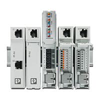
PP-RJ DIN Rail Patch Panels
Easily connect field and control cabinet cabling
- 10/100/1000 Mbps
- RJ45 to RJ45, IDC, Push-in or Screw Terminal Block
- Wiring space covered with front panel cover
- Tool-free shield contacting with strain relief
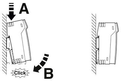
- Compact design with quick and easy mounting
- Extended temperature range of -40°C to +75°C
Ethernet patch panels make the connection between field cabling and control cabinet cabling quick and easy. A PP-RJ DIN Rail Patch Panel is ideal for installation inside control panels and distribution cabinets where one-to-one simplified connections need to be made. A standard Ethernet patch cable is used between the patch panel and the control cabinet equipment, such as switches, PLCs and routers. Through ICD, Push-in, Screw or RJ45 connectors, field wiring is easily connected to the patch panel and protected inside a covered wiring space. The cable shielding is connected quickly and easily, without tools, while simultaneously ensuring strain relief. This simplifies installation of the field cable and saves a great deal of time during installation. PP-RJ DIN Rail Patch Panels provide the perfect mix of density and flexibility to decrease network risk and improve cable organization in scalable deployments with constricted spaces.
Ideal applications for PP-RJ DIN Rail Patch Panels
- Inside equipment cabinets with DIN rails
- Alongside Industrial Ethernet switches and RJ45 (Ethernet or Serial) PLCs
- Alongside other DIN Rail RJ45 (Ethernet or Serial) control devices
- Where growth from one to many ports is needed to support high-density installations. Multiple one port DIN Rail Patch Panels can installed side-by-side to grow, as required by the customer application.
Benefits of PP-RJ DIN Rail Patch Panels
| Multiple connection technologies |
For greater flexibility and time savings during installation you can choose between IDC, Push-in, Screw, and RJ45 connections.
|
| Covered cable wiring space | A hinged cover protects the wiring space on the field cable side with connection terminal blocks and shield contacting. This ensures a uniform installation pattern. In addition to this visual extra, the sensitive connection wires are protected from external influences. |
| Quick tool-free shield connection with no loose parts |
The cable shielding can be connected to the device quickly and easily without tools – with strain relief assured at the same time. Simply lay the cable in the shaft provided, close the shroud and, you're done. 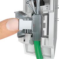
|
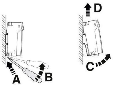
| DIN Rail Enclosure | Easily mount on a DIN rail or inside distribution boxes using native DIN Rail enclosure with grounding clip. No need for add-on brackets. |
| Low profile design | The low-profile design minimizes cable bend radius in shallow enclosures where space is a premium as well as providing secure cable strain relief. |
Specifications
HTSUS Number:
8536.90.8085
UNSPSC Code:
43223309
ECCN:
EAR99


Serial interface
Interface 1
Ethernet interface, 10/100/1000Base-T(X) according to IEEE 802.3u
Connection method
PP-RJ-IDC
27030198
IDC connection
PP-RJ-SCC
27030188
Push-in connection
PP-RJ-SC
27030168
Screw terminal block
PP-RJ-RJ
27030158
RJ45 socket
Transmission length
100 m (including patch cables)
Conductor cross section solid min.
PP-RJ-IDC
27030198
0.14 mm²
PP-RJ-SCC
27030188
0.2 mm²
PP-RJ-SC
27030168
0.14 mm²
PP-RJ-RJ
27030158
Conductor cross section solid max.
PP-RJ-IDC
27030198
0.34 mm²
PP-RJ-SCC
27030188
1.5 mm²
PP-RJ-SC
27030168
1.5 mm²
PP-RJ-RJ
27030158
Conductor cross section flexible min.
PP-RJ-IDC
27030198
0.14 mm²
PP-RJ-SCC
27030188
0.2 mm²
PP-RJ-SC
27030168
0.14 mm²
PP-RJ-RJ
27030158
Conductor cross section flexible max.
PP-RJ-IDC
27030198
0.34 mm²
PP-RJ-SCC
27030188
1.5 mm²
PP-RJ-SC
27030168
1.5 mm²
PP-RJ-RJ
27030158
Conductor cross section AWG min.
PP-RJ-IDC
27030198
26
PP-RJ-SCC
27030188
26
PP-RJ-SC
27030168
28
PP-RJ-RJ
27030158
Conductor cross section AWG max.
PP-RJ-IDC
27030198
22
PP-RJ-SCC
27030188
16
PP-RJ-SC
27030168
16
PP-RJ-RJ
27030158
Wire diameter incl. insulation
PP-RJ-IDC
27030198
1.6 mm (Terminal block is tested with PVC insulation - other insulation materials available on request)
PP-RJ-SCC
27030188
PP-RJ-SC
27030168
PP-RJ-RJ
27030158
Pin assignment
1:1
Serial transmission speed
10/100/1000 Mbps
Output nominal voltage
- < 60 V (ATEX approval)
- < 57 V DC (With UL approval)
Maximum output current
725 mA (Per channel)
Maximum output power
60 W
Interface 2
Ethernet interface, 10/100/1000Base-T(X) according to IEEE 802.3u
Connection method
RJ45 CAT5e
Stripping length
PP-RJ-IDC
27030198
PP-RJ-SCC
27030188
8 mm
PP-RJ-SC
27030168
5 mm
PP-RJ-RJ
27030158
Torque
PP-RJ-IDC
27030198
PP-RJ-SCC
27030188
PP-RJ-SC
27030168
0.22 Nm ... 0.25 Nm
PP-RJ-RJ
27030158
Ambient conditions
Ambient temperature (operation)
-40°C ... 75°C
Ambient temperature (storage/transport)
-40°C ... 85°C
Permissible humidity (operation)
10 % ... 95 % (non-condensing)
Altitude
5000 m (For restrictions see manufacturer's declaration) / 2000 m (ATEX approval)
Degree of protection
IP20 (Manufacturer's declaration)
General
Net weight
PP-RJ-IDC
27030198
104.1 g
PP-RJ-SCC
27030188
124.2 g
PP-RJ-SC
27030168
124.2 g
PP-RJ-RJ
27030158
103.2 g
Housing material
Plastic
Color
Gray
MTTF
105699 Years
Degree of pollution
2
Overvoltage category
II
Conformance
CE-compliant
ATEX
PP-RJ-IDC
27030198
II 3 G Ex nA IIC Gc U
PP-RJ-SCC
27030188
II 3 G Ex nA IIC Gc U
PP-RJ-SC
27030168
II 3 G Ex nA IIC Gc U
PP-RJ-RJ
27030158
II 3 G Ex nA IIC Gc U (Please follow the special installation instructions in the documentation!)
UL, USA
UL 60079-0 Ed. 6 / UL 60079-15 Ed. 4
UL, Canada
CSA 22.2 No. 60079-0 Ed. 3 / CSA 22.2 No. 60079-15:16
Standards and Regulations
Type of test
Vibration resistance in acc. with EN 60068-2-6/IEC 60068-2-6
Test result
10 Hz ... 57 Hz, amplitude ±3.5 mm, 57 Hz ... 150 Hz, 5g
Type of test
Shock in acc. with EN 60068-2-27/IEC 60068-2-27
Test result
30g for 11 ms, three shocks in each spatial direction
Type of test
Continuous shock according to EN 60068-2-27/IEC 60068-2-27
Test result
10g for 16 ms, 1000 shocks in each spatial direction
Rated insulation voltage
85 V DC
Conformance
CE-compliant
ATEX
II 3 G Ex nA IIC Gc U
UL, USA
UL 60079-0 Ed. 6 / UL 60079-15 Ed. 4
UL, Canada
CSA 22.2 No. 60079-0 Ed. 3 / CSA 22.2 No. 60079-15:16
Noxious gas test
ISA-S71.04-1985 G3 Harsh Group A
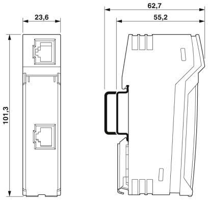
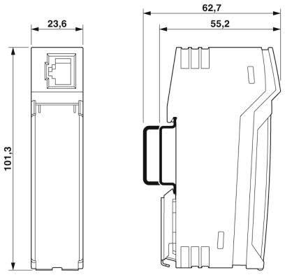
Dimensions
Caption
Compact housing
Width
23.8 mm
Height
101.3 mm
Depth
50 mm
Approvals
- cULus Listed
- cUL Listed
Environmental Product Compliance
China RoHS
PP-RJ-IDC
27030198
Environmentally friendly use period: unlimited = EFUP-e
PP-RJ-SCC
27030188
Environmentally friendly use period: unlimited = EFUP-e
PP-RJ-SC
27030168
Environmentally Friendly Use Period = 50
PP-RJ-RJ
27030158
Environmentally friendly use period: unlimited = EFUP-e
Application Diagrams
Easily Mount your Patch Panel on a DIN Rail
PP-RJ-RJ Patch Panel Dimensional drawing of Compact housing
Two RJ45 Sockets
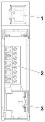
PP-RJ-SC Patch Panel Dimensional drawing of Compact housing
1 x RJ45 socket and 1 x screw terminal block
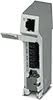
PP-RJ-SCC Patch Panel Dimensional drawing of Compact housing
1 x RJ45 socket and 1 x Push-in terminal block
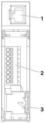
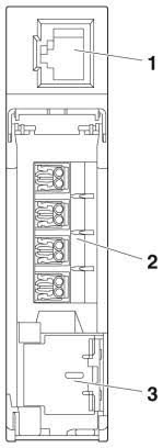
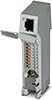
PP-RJ-IDC Patch Panel Dimensional drawing of Compact housing
1 x RJ45 socket and 1 x IDC terminal block
Shield Connection with strain relief
1 x RJ45 socket and 1 x Push-in terminal block
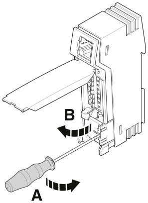 Open shield contact spring
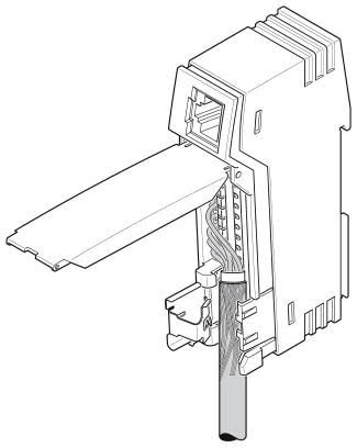 Insert the cable
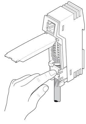 Close shield contact spring
Click on a part number for ordering information
Product Image
Product Description
Power Cord & Part No.
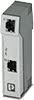
PP-RJ-RJ DIN Rail Patch Panel: two RJ45 sockets, 10/100/1000 Mbps, IP20
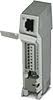
PP-RJ-SC DIN Rail Patch Panel: 1 x RJ45 socket, 1 x screw terminal block, 10/100/1000 Mbps, IP20, shield contacting with strain relief
PP-RJ-SCC DIN Rail Patch Panel: 1 x RJ45 socket, 1 x Push-in terminal block, 10/100/1000 Mbps, IP20, shield contacting with strain relief
PP-RJ-IDC DIN Rail Patch Panel: 1 x RJ45 socket, 1 x IDC terminal block, 10/100/1000 Mbps, IP20, shield contacting with strain relief
