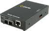
S-110P-XT PoE Industrial Media and Rate Converters
10/100Base-TX to 100Base-X Conversion
- 10/100Base-TX to 100Base-X Fiber
- Supplies IEEE 802.3 PoE & PoE+ PSE power
- Compatible with legacy pre-standard PoE devices
- Fix fiber ports or empty slot for Cisco and other industry standard SFPs
- Advanced features: PD Reset, Smart Link Pass-Through, Fiber Fault Alert, Auto-MDIX and Loopback
- -40F to +167F (-40°C to +75°C) extended temperature support
- Terminal block power connector
The S-110P-XT Industrial Temperature PoE Media Converters address the need for transparently connecting 10/100 Ethernet equipment that operate in extreme temperatures to fiber while providing Power over Ethernet (PoE) to standards-based PoE and PoE+ compliant devices.
The S-110P-XT PoE Media Converters will operate in industrial grade temperatures of -40°F to +167°F (-40°C to +75°C). Equipment found in traffic management, oil and gas pipelines, weather tracking, industrial and outdoor applications must function in temperatures that cannot be supported by a commercial based media converter. Boasting this extended temperature feature along with a rugged steel casing, the S-110P-XT Media Converter provides an economical path to extend the distance between two industrial devices subjected to harsh environments and severe temperatures such as security cameras, wireless access points, alarms, traffic controllers, sensors and tracking devices.
Perle PoE Media Converters are classified as Power Sourcing Equipment (PSE). While using standard UTP cables that carry Ethernet data, Perle PoE media converters also provide power to Powered Devices (PDs). Perle has PoE media converter models that support the IEEE 802.3af PoE standard (15.4W of power) or the IEEE 802.3at PoE+ standard (30W of power). Learn more about PoE.
Perle 10/100 PoE Ethernet to Fiber Converters provide an economical path to extend the distance of an existing network with fiber cabling. At the same time they function as PoE injectors to power devices like IP cameras and Wi-Fi devices over copper UTP cabling.
Network Administrators can "see-everything" with Perle's advanced features such as Auto-Negotiation, Auto-MDIX, Link Pass-Through, Fiber Fault Alert, and Loopback. This allows for more efficient troubleshooting and less on-site maintenance. These cost and time saving features, along with a lifetime warranty and free worldwide technical support, make Perle's S-110P-XT Industrial Temperature 10/100 PoE Media Converters the smart choice for IT professionals.
S-110P-XT Industrial Temperature Copper to Fiber PoE Media Converter Features
|
Power Over Ethernet |
|
|
Advanced Power Management |
|
|
PD Power Reset |
Ideal for remotely resetting equipment, this configurable function performs a momentary power reset to the attached Powered Device (PD). When enabled, the media converter will, upon loss of fiber RX, turn off PSE output power supplied to the PD device for 2 seconds then turn the power back on and leave it on until such time that another fiber RX link is lost (after it was re-established). When disabled, a loss of fiber RX has no effect on PSE power to the PD device(s). |
|
Powered Device Support |
Support is included for a broad range of PD (Powered Devices)
|
|
Power Strain Relief strap |
Included with all models, a strain relief strap is provided to ensure a solid and secure power connection to the media converter. Ideal for areas that may be exposed to vibration. |
|
Auto-Negotiation (802.3u) |
The media converter supports auto negotiation on the 10/100Base-TX interface. |
|
Auto-MDIX |
Auto-MDIX (automatic medium-dependant interface crossover) detects the signaling on the UTP interface to determine the type of cable connected (straight-through or crossover) and automatically configures the connection when enabled. With Auto-MDIX enabled, either a straight-through or crossover type cable can be used to connect the media converter to the device on the other end of the cable. |
|
With Link Pass-Through the state of the UTP receiver is passed to the fiber transmitter to make the media converter appear transparent to the end devices that are connected. In addition if Far-End Fault is enabled the media converter can turn off the 10/100Base-TX transmitter when a FAR-End Fault is received. Using Link Pass-Through with Far-End Fault minimizes data loss when a fault occurs. Should a fault occur, the end devices have the indication of a failure available to them making trouble shooting easier. |
|
|
Far-End Fault (FEF) |
The media converter implements the 802.3 standard for Far-End Fault for the indication and detection of remote fault conditions on the 100Base-X fiber connection. With Far-End Fault enabled the media converter transmits the Far-End Fault Indication over the 100Base-X fiber connection whenever a receive failure is detected on the 100Base-X fiber connection. The media converter continuously monitors the 100Base-X fiber connection for a valid signal. The action the media converter takes on receiving a Far-End Fault Indication is dependent on the Link Pass-Through switch setting. |
|
Pause (IEEE 802.3xy) |
Pause signaling is an IEEE feature that temporarily suspends data transmission between two devices in the event that one of the devices becomes overwhelmed. The media converter supports pause negotiation on the 10/100Base-TX copper connection. |
|
Duplex |
Full and half duplex operation supported. |
|
VLAN |
Transparent to VLAN tagged packets. |
|
Remote Loopback |
Capable of performing a loopback on the 100Base-X fiber interface. |
Specifications
HTSUS Number:
8517.62.0020
UNSPSC Code:
43201553
ECCN:
5A991


Power
Input Supply Voltage
- PoE models: 46 - 57 vDC
- PoE+ models: 52 - 57 vDC
Power Consumption
3.5 Watts
Power Over Ethernet (PSE)
- PoE models: maximum to 15.4 watts supplied to port
- PoE+ models: up to 30 watts supplied to port
PoE Options
Alternative A (power on pins 1,2 and 3,6)
Alternative B (power on pins 4,5 and 7,8)
- Legacy PoE (IE wireless access points) - (reverse polarity on pins 4,5 and 7,8)
- Legacy large capacitor detect (pins 4,5 and 7,8)
Power Connector
2 pin pluggable terminal block
Indicators
Power (PWR)
This green LED is turned on when power is applied to the media converter. Otherwise it is off. The LED will blink slowly when either fiber port is in Loopback test mode. The LED will blink quickly if there is a hardware failure where the reason code can be identified through a various blinking cycles.
Fiber link on / Receive activity (LKF 1/2)
- This green LED is operational only when power is applied. The LED will blink along with transmit/receive data on the fiber port
- If a loss of link on the copper port results in a Link Passthrough condition to the fiber port, this LED will blink at a rate of once every 2 seconds until the condition is cleared.
Copper link on / Receive activity (LKC 1/2)
- This green LED is operational only when power is applied. The LED will blink along with transmit/receive data on the 10/100/1000 UTP port
- If a loss of link on the copper port results in a Link Passthrough condition to the fiber port, this LED will blink at a rate of once every 2 seconds until the condition is cleared.
10/100 Speed
This green LED is operational only when power is applied. The LED is green when the speed of the copper ethernet port is running at 100 Mbps. The LED is off when in 10 Mbps.
PSE Status
This LED will signify the status of the PSE function. Using multi-color and blinking the unit will show the following status for the PSE;GREEN — Solid: The PSE has successfully detected a compliant PD and is applying power over the UTP (for legacy pin out simply show active power when applied)
YELLOW — Solid: The PSE is not active. This means the PSE has been configured to provide power, but the PD is :
- Not connected
- Has not detected a compliant PD and is not applying power
- PSE has turned off power for Reset function
OFF — PSE function switch disabled
RED — Blinking: Error Conditions
- Capacitance too High — 1 blink
- Resistance too Low or short circuit — 2 blinks
- Resistance too high or open circuit — 3 blinks
Switches
Auto-Negotiation (802.3u)
- Enabled (Default) - The media converter uses 802.3u Auto-negotiation on the 100Base-TX interface. It is set to advertise full duplex.
- Disabled - The media converter sets the port according to the position of the speed and duplex switches.
Link Pass Through
- Disabled (Default) - The 100Base-TX and the 100Base-FX fiber interface operate independently. Far-End Fault indication on the 100Base-FX fiber interface has no effect on the 100Base-TX interface.
- Enabled - When the state of the receiver is changed on the 100Base-TX interface it is reflected on the 100Base-FX fiber transmitter. When the state of the receiver on the 100Base-FX interface is changed it is reflected on the 100Base-TX transmitter.
When a Far-End Fault Indication is received on the fiber interface the 100Base-TX transmitter is turned off. When the Far-End Fault Indication is cleared the transmitter is turned back on.
Far-End Fault (FEF)
- Enabled (Default) - The media converter transmits the Far-End Fault Indication over the 100Base-X fiber connection whenever a receive failure is detected on the 100Base-X fiber connection. The media converter continuously monitors the 100Base-X fiber connection and clears the Far-End Fault Indication condition when a valid signal is received.
- Disabled - Far-End Fault Indications are not transmitted regardless of the condition of the receive signal on the 100Base-FX fiber connection.
Remote Loopback
- Disabled (Default - Up)
- Enabled- The 100Base-X receiver is looped to the 100Base-X transmitter. The 100Base-TX transmitter is taken off the interface.
Speed Copper
(internal strap)
- 100 (Default)
- 10
Duplex Copper
(internal strap)
- Full (Default)
- Half
Auto-MDIX
(Internal Strap)
If Auto-Negotiation (802.3u) is enabled, the media converter determines the current cable pinout to use on the copper interface. If Auto-Negotiation (802.3u) is disabled the Media converter will use the RX Energy method on the copper interface to set the port MDI or MDIX whichever is appropriate.
- Enabled (Default) - Either a straight-through or crossover type cable can be used to connect the media converter to the device on the other end of the cable.
- Disabled - If the partner device on the other end of the cable does not have the Auto-MDIX feature a specific cable, either a straight-through or crossover will be required to ensure that the media converter's transmitter and the partner devices transmitter are connected to the others receiver. The Media converter's 100Base-TX port is configured as MDI-X with this switch setting.
PSE Power
When enabled (UP), the media converter will perform a Power Sourcing Equipment (PSE) function as per IEEE802.3af or 802.3at standards (relevant model).
Default is 'enabled'
PD Power Reset
This is a technique to perform a power reset on a PD device attached.
- When enabled (down), the media converter will upon loss of link on any fiber port, turn off PSE output power to the PD device for 2 seconds then turn the power back on. The power remains on until any fiber link transitions from up to down again.
- With Passthrough enabled, a loss of link on the fiber resulting from a loss of link on the copper, a PD Power Reset will occur and the copper link will continue to reflect the state of the fiber link.
- When PD Power Reset disabled, loss of fiber link has no effect on PSE power to the PD device.
PoE Power Options
(Internal Straps)
- Set to Alternative A (default): Pins 3,6 Neg, Pins 1,2 Pos
- Set to Alternative B: Pins 7,8 Neg, Pins 4,5 Pos
- Set to Legacy Pre-Standard: Pins 7,8 Pos, Pins 4,5 Neg
Connectors
10/100Base-TX
RJ45 connector.
2 pair CAT5, EIA/TIA 568A/B or better cable for 10/100.
Magnetic Isolation
1.5kv
Fixed Fiber
- Dual multimode or single mode (Duplex) fiber - SC, ST
- Single strand fiber (Simplex) - SC
- LC - obtained by inserting an SFP (LC) in an SFP slot model
Small Form Factor Pluggable (SFP) slot
SFP slot models: Empty slot for 100Base-X SFP modules supplied by Perle, Cisco or other manufacturers of MSA compliant SFPs.
Hot insertion and removable (hot swappable)
Filtering
Filtering
1024 MAC Addresses
Frame Specifications
Buffer
1000 Kbits frame buffer memory
Size
Maximum frame size of 2048 bytes
Environmental Specifications
Operating Temperature
-40°C to 75°C (-40°F to 167°F)
Storage Temperature
-40°C to 85°C (-40°F to 185°F)
Operating Humidity
5% to 90% non-condensing
Storage Humidity
5% to 95% non-condensing
Operating Altitude
Up to 3,048 meters (10,000 feet)
Heat Output (BTU/HR)
12
MTBF (Hours)*
SFP Slot: 446,216 Hours
Fixed Fiber: 392,490 Hours
Calculation model based on MIL-HDBK-217-FN2 @ 30°C
Chassis
Metal with an IP20 ingress protection rating
Mounting
Din Rail Kit
Optional
Rack Mount Kit
Optional
Product Weight and Dimensions
Weight
0.3 Kg, 0.7 lbs (No power adapter)
Dimensions
120 x 80 x 26 mm, 4.7 x 3.1 x 1.0 inches
Packaging
Shipping Weight
0.425 kg, 0.9 lbs
Shipping Dimensions
150 x 210 x 40 mm, 5.9 x 11 x 2.8 inches
Regulatory Approvals
Emissions
- FCC Part 15 Class A
- CISPR 32 / EN 55032
- EN61000-3-2
Immunity
CISPR 35 / EN 55035
Electrical Safety
- UL/EN/IEC 62368-1
- CAN/CSA C22.2 No. 62368-1
- UL 60950-1
- IEC 60950-1(ed 2); am1, am2
- EN 60950-1:2006+A11:2009+A1:2010+A12:2011+A2:2013
- CE
Laser Safety
- EN 60825-1
- Fiber optic transmitters on this device meet Class 1 Laser safety requirements per IEC-60825 FDA/CDRH standards and comply with 21CFR1040.10 and 21CFR1040.11.
Application Diagrams
Fast Ethernet to IP Cameras
Extend the reach to IP cameras using industrial fiber PoE media converters. Security cameras are typically installed in remote locations where extremely high or low temperatures are a concern -- ceilings, rooftops, light poles, along fences, pipelines and transit routes. The cost of bringing electrical power to each camera located in these inaccessible areas is eliminated by powering the equipment through the UTP cable using a PoE media converter. For cameras with Pan-Tilt-Zoom ( PTZ ) that may require higher power, PoE+ models that can supply up to 30 watts of power are also available. PoE+ may also be required for cameras used in cold environments that feature de-icers and blowers.
Fiber is run from an existing data closet to an area with access to power. A PoE Media Converter can be powered by either 48vDC or standard 100 to 240 AC power. The media converter is attached to the power supply and the fiber cable. Copper (UTP or STP cable) Ethernet can be extended another 100 meters to the IP camera. The PoE Media Converter is converting the data from fiber to copper, adding power and transmitting it to the security camera.
Fast Ethernet Fiber to Wireless Access Points
Extend the reach to wireless access points ( AP ) using fiber PoE media converters. When a company deploys a wireless network in their office or large warehouse, APs need to be set up throughout the facility to ensure complete coverage for reliability. The network manager will likely need to extend further than the 100 meters allowed by copper cable to reach many of the APs.
For APs that are in the ceiling or other inaccessible areas, PoE media converters can also provide standard PoE power including pre-standard power for those access points that were deployed prior to ratification IEEE 802.3af. For wireless access points as those containing dual radios requiring more than 15.4 watts of power, PoE+ models delivering up to 30 watts are also available.
When AP’s are used in industrial environments where extremely high or low temperatures are a concern, fiber is run from an existing data closet to an area with access to power. A PoE Media Converter can be powered by either 48vDC or standard 100 to 240 AC power. The media converter is attached to the power supply and the fiber cable. Copper (UTP or STP cable) Ethernet can be extended another 100 meters to the Wireless Access Point. The PoE Media Converter is converting the data from fiber to copper, adding power and transmitting it to the AP.
Single Mode / Single Fiber
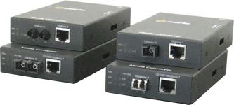
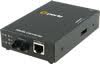
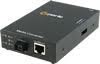
When Single Strand fiber is used, a pair of Single Fiber Media Converters is needed for the copper to fiber conversion. Perle Single Fiber Media Converters are also referred to as “Up/Down” models. For example S-110P-S1SC20U-XT (“Up”) and S-110P-S1SC20D-XT (“Down”), shown below, must be used in pairs. An “Up” must be matched with a “Down” peer to deal with transmit and receive frequencies separately.
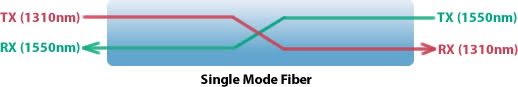
S-110P-S1SC20U-XTS-110P-S1SC20D-XT
The majority of installations for single mode fiber media converters are of the “dual connector” or “dual fiber” type where one fiber connection is used for transmit, the other for receive. These are physically “crossed” to match up the Transmit/Receive links.
However, to reduce costs, or where there are limits on available fiber, WDM technology may be utilized. WDM uses separate transmit and receive frequencies to communicate on a single fiber strand. WDM technology relies on the fact that optical fibers can carry many wavelengths of light simultaneously without interaction between each wavelength. Thus, a single fiber can carry many separate wavelength signals or channels simultaneously.
So remember, if Single Strand fiber is used, you will need an “Up” Media Converter on one side and a “Down” Media Converter on the other for copper to fiber conversion.


Select a Model to obtain a Part Number - S-110P-XT Industrial Temperature PoE Media Converter
Model |
Fiber Port
Connector |
Type |
Transmit
(dBm) |
Receive
(dBm) |
Power
Budget (dBm) |
Wavelength
(nm) |
Fiber
Type |
Operating
Distance |
||
|---|---|---|---|---|---|---|---|---|---|---|
| Min | Max | Min | Max | |||||||
| S-110P-SFP-XT | 1 x SFP / LC |
100Base-X |
- |
- |
- |
- |
- |
- |
MMF/SMF |
- |
| S-110P-M2SC2-XT | Dual SC |
100Base-FX |
-20.0 |
-12.0 |
-31 |
-14.0 |
11.0* |
1310 |
MMF |
2 km
(1.2 mi) |
| S-110P-M2ST2-XT | Dual ST |
100Base-FX |
-20.0 |
-12.0 |
-31 |
-14.0 |
11.0* |
1310 |
MMF |
2 km
(1.2 mi) |
| S-110P-S2SC20-XT | Dual SC |
100Base-LX |
-18.0 |
-7.0 |
-32 |
-3.0 |
14.0 |
1310 |
SMF |
20 km
(12.4 mi) |
| S-110P-S2ST20-XT | Dual ST |
100Base-LX |
-18.0 |
-7.0 |
-32 |
-3.0 |
14.0 |
1310 |
SMF |
20 km
(12.4 mi) |
Single Fiber Models Recommended use in pairs
Model |
Fiber Port
Connector |
Type |
Transmit
(dBm) |
Receive
(dBm) |
Power
Budget (dBm) |
Wavelength
(nm) |
Fiber
Type |
Operating
Distance |
||
|---|---|---|---|---|---|---|---|---|---|---|
| Min | Max | Min | Max | |||||||
| S-110P-S1SC20U-XT | Single SC |
100Base-BX-U |
-14.0 |
-8.0 |
-32 |
-3.0 |
18.0 |
1310 / 1550 |
SMF |
20 km
(12.4 mi) |
| S-110P-S1SC20D-XT | Single SC |
100Base-BX-D |
-14.0 |
-8.0 |
-32 |
-3.0 |
18.0 |
1550 / 1310 |
SMF |
20 km
(12.4 mi) |
The minimum fiber cable distance for all converters listed is 2 meters.
*Based on use with 62.5/125 micron multimode fiber.
Select a Model to obtain a Part Number - 10/100 PoE+ Media Converter
Model |
Fiber Port
Connector |
Type |
Transmit
(dBm) |
Receive
(dBm) |
Power
Budget (dBm) |
Wavelength
(nm) |
Fiber
Type |
Operating
Distance |
||
|---|---|---|---|---|---|---|---|---|---|---|
| Min | Max | Min | Max | |||||||
| S-110PP-SFP-XT | 1 x SFP / LC |
100Base-X |
- |
- |
- |
- |
- |
- |
MMF/SMF |
- |
| S-110PP-M2SC2-XT | Dual SC |
100Base-FX |
-20.0 |
-12.0 |
-31 |
-14.0 |
11.0* |
1310 |
MMF |
2 km
(1.2 mi) |
| S-110PP-M2ST2-XT | Dual ST |
100Base-FX |
-20.0 |
-12.0 |
-31 |
-14.0 |
11.0* |
1310 |
MMF |
2 km
(1.2 mi) |
| S-110PP-S2SC20-XT | Dual SC |
100Base-LX |
-18.0 |
-7.0 |
-32 |
-3.0 |
14.0 |
1310 |
SMF |
20 km
(12.4 mi) |
| S-110PP-S2ST20-XT | Dual ST |
100Base-LX |
-18.0 |
-7.0 |
-32 |
-3.0 |
14.0 |
1310 |
SMF |
20 km
(12.4 mi) |
Single Fiber Models Recommended use in pairs
Model |
Fiber Port
Connector |
Type |
Transmit
(dBm) |
Receive
(dBm) |
Power
Budget (dBm) |
Wavelength
(nm) |
Fiber
Type |
Operating
Distance |
||
|---|---|---|---|---|---|---|---|---|---|---|
| Min | Max | Min | Max | |||||||
| S-110PP-S1SC20U-XT | Single SC |
100Base-BX-U |
-14.0 |
-8.0 |
-32 |
-3.0 |
18.0 |
1310 / 1550 |
SMF |
20 km
(12.4 mi) |
| S-110PP-S1SC20D-XT | Single SC |
100Base-BX-D |
-14.0 |
-8.0 |
-32 |
-3.0 |
18.0 |
1550 / 1310 |
SMF |
20 km
(12.4 mi) |
The minimum fiber cable distance for all converters listed is 2 meters.
*Based on use with 62.5/125 micron multimode fiber.
Filter your options to find the right hardware for your application
Viewing 12 of 12 products
Click on a part number for ordering information
Product Image
Product Description
Power Cord & Part No.
S-110P-M2SC2-XT - 10/100 Fast Ethernet Stand-Alone Industrial Temperature Media Rate Converter with PoE Power Sourcing. 10/100Base-TX (RJ-45) [100 m/328 ft.] to 100Base-FX 1310nm multimode (SC) [2 km/1.2 miles]. Extended Temperature, terminal block power connector for external power source.
S-110P-M2ST2-XT - 10/100 Fast Ethernet Stand-Alone Industrial Temperature Media Rate Converter with PoE Power Sourcing. 10/100Base-TX (RJ-45) [100 m/328 ft.] to 100Base-FX 1310nm multimode (ST) [2 km/1.2 miles]. Extended Temperature, terminal block power connector for external power source.
S-110P-S2SC20-XT - 10/100 Fast Ethernet Stand-Alone Industrial Temperature Media Rate Converter with PoE Power Sourcing. 10/100Base-TX (RJ-45) [100 m/328 ft.] to 100Base-LX 1310nm single mode (SC) [20 km/12.4 miles]. Extended Temperature, terminal block power connector for external power source.
S-110P-S2ST20-XT - 10/100 Fast Ethernet Stand-Alone Industrial Temperature Media Rate Converter with PoE Power Sourcing. 10/100Base-TX (RJ-45) [100 m/328 ft.] to 100Base-LX 1310nm single mode (ST) [20 km/12.4 miles]. Extended Temperature, terminal block power connector for external power source.
S-110P-S1SC20U-XT - 10/100 Fast Ethernet Stand-Alone Industrial Temperature Media Rate Converter with PoE Power Sourcing. 10/100Base-TX (RJ-45) [100 m/328 ft.] to 100Base-BX 1310nm TX / 1550nm RX single strand fiber, single mode (SC) [20 km/12.4 miles]. Extended Temperature, terminal block power connector for external power source.
S-110P-S1SC20D-XT - 10/100 Fast Ethernet Stand-Alone Industrial Temperature Media Rate Converter with PoE Power Sourcing. 10/100Base-TX (RJ-45) [100 m/328 ft.] to 100Base-BX 1550nm TX / 1310nm RX single strand fiber, single mode (SC) [20 km/12.4 miles]. Extended Temperature, terminal block power connector for external power source.
S-110PP-M2SC2-XT - 10/100 Fast Ethernet Stand-Alone Industrial Temperature Media Rate Converter with PoE+ ( PoEP ) Power Sourcing. 10/100Base-TX (RJ-45) [100 m/328 ft.] to 100Base-FX 1310nm multimode (SC) [2 km/1.2 miles]. Extended Temperature, terminal block power connector for external power source.
S-110PP-M2ST2-XT - 10/100 Fast Ethernet Stand-Alone Industrial Temperature Media Rate Converter with PoE+ ( PoEP ) Power Sourcing. 10/100Base-TX (RJ-45) [100 m/328 ft.] to 100Base-FX 1310nm multimode (ST) [2 km/1.2 miles]. Extended Temperature, terminal block power connector for external power source.
S-110PP-S2SC20-XT - 10/100 Fast Ethernet Stand-Alone Industrial Temperature Media Rate Converter with PoE+ ( PoEP ) Power Sourcing. 10/100Base-TX (RJ-45) [100 m/328 ft.] to 100Base-LX 1310nm single mode (SC) [20 km/12.4 miles]. Extended Temperature, terminal block power connector for external power source.
S-110PP-S2ST20-XT - 10/100 Fast Ethernet Stand-Alone Industrial Temperature Media Rate Converter with PoE+ ( PoEP ) Power Sourcing. 10/100Base-TX (RJ-45) [100 m/328 ft.] to 100Base-LX 1310nm single mode (ST) [20 km/12.4 miles]. Extended Temperature, terminal block power connector for external power source.
S-110PP-S1SC20U-XT - 10/100 Fast Ethernet Stand-Alone Industrial Temperature Media Rate Converter with PoE+ ( PoEP ) Power Sourcing. 10/100Base-TX (RJ-45) [100 m/328 ft.] to 100Base-BX 1310nm TX / 1550nm RX single strand fiber, single mode (SC) [20 km/12.4 miles]. Extended Temperature, terminal block power connector for external power source.
S-110PP-S1SC20D-XT - 10/100 Fast Ethernet Stand-Alone Industrial Temperature Media Rate Converter with PoE+ ( PoEP ) Power Sourcing. 10/100Base-TX (RJ-45) [100 m/328 ft.] to 100Base-BX 1550nm TX / 1310nm RX single strand fiber, single mode (SC) [20 km/12.4 miles]. Extended Temperature, terminal block power connector for external power source.