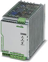
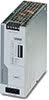
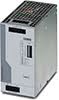
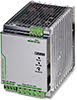
QUINT-PS/3AC – 3-Phase DIN Rail Power Supply
Robust with SFB (Selective Fuse Breaking) Technology & NFC
- Output Voltages: 24 or 48 V DC
- Adjustable Output Voltage Ranges: 18 to 56 V DC
- Output Amps: 10, 20 or 40 Amps
- Output Watts: 240, 480 or 960 W
- Will operate with 3-phase or 2-phase AC or DC input Voltage Ranges
QUINT 3-Phase Power Supplies offer a range of rugged AC to DC and DC to DC Converters built to meet the high stability and efficiency expectations of industrial, machine automation and process control environments. They also feature the unique combination of preventive function monitoring and power reserve in an incredibly compact size. Perfect for use in high power applications, these Switching (switch mode) Power Supplies ensure a regulated output voltage even in the event of voltage fluctuations in the power supply network. During parallel operation, and when connected to different phases, loads are reliably supplied even in the event of problems with the input voltage. With all required safety certifications to support ITE (Information Technology Equipment), ruggedized packaging, extended operating temperatures, high peak load capabilities and high isolation voltages, QUINT Industrial Power Supplies are designed to meet the needs of your industrial application.
POWER BOOST: reliably start difficult loads
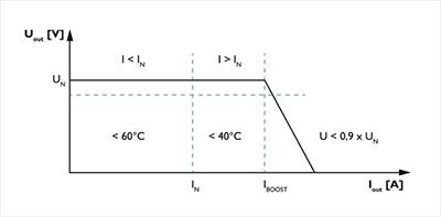
A high degree of flexibility is required to configure, optimize and expand large systems. To optimally adapt a system or machine to your requirements, a power reserve in the power supply unit is crucial. The QUINT supplies up to 50% additional current without a voltage drop. This is useful when it is not possible to predict which loads will be switched on at the same time or high switch-on currents of capacitive loads have to be absorbed without voltage dips. With the QUINT Power Boost function a static boost will continuously provide up to 125% of the nominal current. In addition, you can use the dynamic boost to supply up to 200% of the nominal current for 5 seconds when starting up heavy loads.
Preventive function monitoring reports critical operating states before they occur
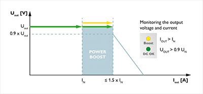
With a QUINT Industrial Power Supply, the output voltage and output current are constantly monitored. Preventive function monitoring visualizes critical operating states and indicates them locally and remotely to the controller as follows:
- Via LED
- Via floating relay contact
- Via active switching output
Industrial operating temperature of -25°C to +70°C
Equipment found in traffic management, oil and gas pipelines, weather tracking, industrial and outdoor applications must function in temperatures that cannot be supported by a commercial power supplies. With an operating temperature of -25°C to +70°C, and reliable device start-up at -40°C, the QUINT Industrial Power Supply is ideal for use with equipment subjected to harsh environments and severe temperatures.
High efficiency and low no load power consumption
Compared with other products on the market, the QUINT Industrial Power Supply provides excellent energy savings. With a very low no load power consumption and high efficiency at nominal load, just a small amount of electrical energy is converted into undesired heat energy making these very ECO friendly power supplies.
SFB (Selective Fuse Breaking) Technology
SFB Technology can be used to quickly and reliably trip miniature circuit breakers and fuses connected on the secondary side. In the event of a short circuit on the secondary side, the QUINT supplies up to 6 times the nominal current for 15 ms. Faulty current paths are switched off selectively, the fault is located, and important system parts remain in operation. Loads that are connected in parallel are still supplied with energy ensuring continued operation of these system parts.
- Tripping circuit breakers: The circuit breaker is typically tripped by the high SFB current within 3 to 5 ms. As a result, any voltage dips for loads connected in parallel are avoided.
- Tripping a fuse: Fuses are tripped by melting the predetermined breaking point inside the fuse capsule. The tripping characteristic of the fuse is described by the melting integral (I²t). A high current is crucial in order to achieve a very short tripping time.

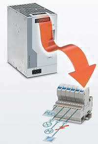
Near Field Communication (NFC)
Near Field Communication (NFC) is a transmission standard for wireless and contactless data exchange at a close distance. With NFC, you can easily parameterize QUINT Power Supply settings such as define signaling thresholds for preventive function monitoring, adjust output voltage, and adapt the output characteristic curve to your specific requirements using a PC, mobile phone, or mobile terminal device. You can also save and send configuration profiles on your mobile terminal device. QUINT Power NFC App on the Google Play Store.
Ideal application environments for a QUINT 3-Phase Power Supply
- Drive motors and other devices
- Machine building
- Automated production process
- Industrial control, automation, assembly, and test equipment
- Building control, security and surveillance, and climate control systems.
- Power countless industrial automation devices such as sensors, controllers and valves
Other reasons to choose a QUINT 3-Phase Power Supply
- Robust input side: high noise immunity, integrated gas-filled surge arrester (up to 6 kV), and ≥ 20 ms mains failure buffer time
- Narrow, slim-line design saves space in the control box
- Voltage Isolation input/output: 4 kV AC
- Protections: Short-circuit, Overload, Over voltage, Over-temperature
- High MTBF (Mean Time Between Failure) values
Specifications
HTSUS Number:
QUINT-PS/3AC/48DC/20: 8504.40.7018, QUINT-PS/3AC/24DC/40: 8504.40.7018, QUINT4-PS/3AC/24DC/10: 8504.40.7012, QUINT4-PS/3AC/24DC/20: 8504.40.7012
UNSPSC Code:
39121004
ECCN:
EAR99

Environmental Product Compliance
REACH SVHC
23208278
Lead 7439-92-1
28668028
Lead 7439-92-1
29046218
Lead 7439-92-1
29046228
Lead 7439-92-1
China RoHS
Environmentally Friendly Use Period = 25;
General
Net weight
23208278
2.5 kg
28668028
2.5 kg
29046218
0.9 kg
29046228
1.1 kg
Efficiency
23208278
> 93 % (at 400 V AC and nominal values)
28668028
> 94 % (at 400 V AC and nominal values)
29046218
typ. 93 % (400 V AC)
29046228
typ. 93.9 % (400 V AC)
Insulation voltage input/output
23208278
- 4 kV AC (type test)
- 2 kV AC (routine test)
28668028
- 4 kV AC (type test)
- 2 kV AC (routine test)
29046218
- 4 kV AC (type test)
- 2.4 kV AC (routine test)
29046228
- 4 kV AC (type test)
- 2.4 kV AC (routine test)
Insulation voltage input / PE
23208278
- 3.5 kV AC (type test)
- 2 kV AC (routine test)
28668028
- 3.5 kV AC (type test)
- 2 kV AC (routine test)
29046218
- 3.5 kV AC (type test)
- 2.4 kV AC (routine test)
29046228
- 3.5 kV AC (type test)
- 2.4 kV AC (routine test)
Insulation voltage output / PE
23208278
500 V DC (routine test)
28668028
500 V DC (routine test)
29046218
0.5 kV DC (type test)
29046228
0.5 kV DC (type test)
Protection class
I
Degree of protection
IP20
MTBF (IEC 61709, SN 29500)
23208278
889679,72 h (25°C)
501504,51 h (40°C)
216825,67 h (60°C)
28668028
> 880000 h (25°C)
> 500000 h (40°C)
> 216000 h (60°C)
29046218
> 1034000 h (25°C)
> 654000 h (40°C)
> 320000 h (60°C)
29046228
> 985000 h (25°C)
> 638000 h (40°C)
> 311000 h (60°C)
Mounting position
horizontal DIN rail NS 35, EN 60715
Assembly instructions
alignable: PN ≥50%,
5 mm horizontally
15 mm next to active components
50 mm vertically alignable: PN <50%
0 mm horizontally
40 mm vertically top
20 mm vertically bottom
Operating voltage display
23208278
28668028
Green LED
29046218
29046228
Efficiency
23208278
28668028
29046218
typ. 92.6 % (480 V AC)
29046228
typ. 93.8 % (480 V AC)
Insulation voltage output / PE
23208278
28668028
29046218
0.5 kV DC (routine test)
29046228
0.5 kV DC (routine test)
Standards and Regulations
Electromagnetic compatibility
Conformance with EMC Directive 2014/30/EU
Noise immunity
23208278
EN 61000-6-2:2005
28668028
EN 61000-6-2:2005
29046218
Immunity according to EN 61000-6-1 (residential), EN 61000-6-2 (industrial), and EN 61000-6-5 (power station equipment zone), IEC/EN 61850-3 (energy supply)
29046228
Immunity according to EN 61000-6-1 (residential), EN 61000-6-2 (industrial), and EN 61000-6-5 (power station equipment zone), IEC/EN 61850-3 (energy supply)
Connection in acc. with standard
23208278
CSA
28668028
CSA
29046218
29046228
Standards/regulations
EN 61000-4-2
Contact discharge
4 kV (Test Level 2)
Standards/regulations
EN 61000-4-3
Frequency range
80 MHz ... 1 GHz
Test field strength
10 V/m (Test Level 3)
Frequency range
1.4 GHz ... 2 GHz
Test field strength
3 V/m (Test Level 2)
Standards/regulations
EN 61000-4-4
Comments
Criterion B
Standards/regulations
23208278
EN 61000-4-6
28668028
EN 61000-6-3
29046218
EN 61000-4-6
29046228
EN 61000-4-6
Frequency range
0.15 MHz ... 80 MHz
Voltage
10 V (Test Level 3)
Low Voltage Directive
23208278
Conformance with LV directive 2006/95/EC
28668028
Conformance with LV directive 2006/95/EC
29046218
Conformance with Low Voltage Directive 2014/35/EC
29046228
Conformance with Low Voltage Directive 2014/35/EC
Standard - Safety of transformers
23208278
IEC 61558-2-17
28668028
29046218
EN 61558-2-16 (air clearances and creepage distances only)
29046228
EN 61558-2-16 (air clearances and creepage distances only)
Standard - Electrical safety
IEC 60950-1/VDE 0805 (SELV)
Standard – Electronic equipment for use in electrical power installations and their assembly into electrical power installations
23208278
EN 50178/VDE 0160 (PELV)
28668028
EN 50178/VDE 0160 (PELV) / Overvoltage category III
29046218
EN 50178/VDE 0160 (PELV)
29046228
EN 50178/VDE 0160 (PELV)
Standard - Safe isolation
DIN VDE 0100-410
Standard – Protection against shock currents, basic requirements for protective separation in electrical equipment
23208278
EN 50178
28668028
29046218
29046228
Standard – Limitation of mains harmonic currents
EN 61000-3-2
Standard - Equipment safety
23208278
BG (design tested)
28668028
GS (tested safety)
29046218
29046228
Standard - Approval for medical use
23208278
IEC 60601-1, 2 x MOOP
28668028
29046218
29046228
UL approvals
23208278
- UL/C-UL listed UL 508
- UL/C-UL Recognized UL 60950-1 (3-wire + PE, star net)
- UL ANSI/ISA-12.12.01 Class I, Division 2, Groups A, B, C, D (Hazardous Location)
28668028
- UL/C-UL listed UL 508
- UL/C-UL Recognized UL 60950-1 (3-wire + PE, star net)
- UL ANSI/ISA-12.12.01 Class I, Division 2, Groups A, B, C, D (Hazardous Location)
29046218
- UL/C-UL listed UL 508
- UL/C-UL Recognized UL 60950-1
- UL ANSI/ISA-12.12.01 Class I, Division 2, Groups A, B, C, D (Hazardous Location)
29046228
- UL/C-UL listed UL 508
- UL/C-UL Recognized UL 60950-1
- UL ANSI/ISA-12.12.01 Class I, Division 2, Groups A, B, C, D (Hazardous Location)
Shock
18 ms, 30g, in each space direction (according to IEC 60068-2-27)
Vibration (operation)
23208278
< 15 Hz, amplitude ±2.5 mm (according to IEC 60068-2-6)
15 Hz ... 150 Hz, 2.3g, 90 min.
28668028
5 Hz ... 100 Hz resonance search 2.3g, 90 min., resonance frequency 2.3g, 90 min. (according to DNV GL Class C)
29046218
5 Hz ... 100 Hz resonance search 2.3g, 90 min., resonance frequency 2.3g, 90 min. (according to DNV GL Class C)
29046228
5 Hz ... 100 Hz resonance search 2.3g, 90 min., resonance frequency 2.3g, 90 min. (according to DNV GL Class C)
Information technology equipment - safety (CB scheme)
23208278
CB Scheme
28668028
CB Scheme
29046218
29046228
Rail applications
23208278
EN 50121-4
28668028
EN 50121-4
29046218
EN 50121-3-2
29046228
EN 50121-3-2
Overvoltage category (EN 62477-1)
23208278
III
28668028
III
29046218
III (≤ 2000 m)
29046228
III (≤ 2000 m)
Standards/regulations
23208278
28668028
EN 61000-4-6
29046218
EN 61000-4-8
29046228
EN 61000-4-8
Standard - Safe isolation
23208278
28668028
DIN VDE 0106-101
29046218
29046228
Shipbuilding approval
23208278
28668028
DNV GL (EMC A), ABS, LR, RINA, NK, BV
29046218
DNV GL, PRS, BV, LR, ABS
29046228
DNV GL, PRS, BV, LR, ABS
Noise emission
23208278
28668028
29046218
Additional basic standard EN 61000-6-5 (immunity in power station), IEC/EN 61850-3 (energy supply)
29046228
Additional basic standard EN 61000-6-5 (immunity in power station), IEC/EN 61850-3 (energy supply)
Conducted noise emission
23208278
28668028
29046218
EN 55016 EN 61000-6-4 (Class A)
29046228
EN 55016 EN 61000-6-4 (Class A)
Standards/regulations
23208278
28668028
29046218
- EN 61000-4-11
- EN 61000-4-9
- EN 61000-4-12
- EN 61000-4-16
- EN 61000-4-18
29046228
- EN 61000-4-11
- EN 61000-4-9
- EN 61000-4-12
- EN 61000-4-16
- EN 61000-4-18
Standard - power supply devices for low voltage with DC output
23208278
28668028
29046218
EN 61204-3
29046228
EN 61204-3
EMC requirements, power plant
23208278
28668028
29046218
- IEC 61850-3
- EN 61000-6-5
29046228
Approval - requirement of the semiconductor industry with regard to mains voltage dips
23208278
28668028
29046218
SEMI F47-0706; EN 61000-4-11
29046228
SEMI F47-0706; EN 61000-4-11
Overvoltage category (EN 60950-1)
23208278
28668028
29046218
II (≤ 5000 m)
29046228
II (≤ 5000 m)
Overvoltage category (EN 61010-1)
23208278
28668028
29046218
II (≤ 5000 m)
29046228
II (≤ 5000 m)
Connection data, input
Connection method
Screw connection
Conductor cross section solid min.
0.2 mm²
Conductor cross section solid max.
6 mm²
Conductor cross section flexible min.
0.2 mm²
Conductor cross section flexible max.
4 mm²
Conductor cross section AWG min.
23208278
18
28668028
18
29046218
30
29046228
30
Conductor cross section AWG max.
10
Stripping length
23208278
7 mm
28668028
7 mm
29046218
8 mm
29046228
8 mm
Screw thread
23208278
M4
28668028
M3
29046218
29046228
Output data
Nominal output voltage
23208278
48 V DC ±1 %
28668028
24 V DC ±1 %
29046218
24 V DC
29046228
24 V DC
Setting range of the output voltage (USet)
23208278
30 V DC ... 56 V DC (> 48 V DC, constant capacity restricted)
28668028
18 V DC ... 29.5 V DC (> 24 V DC, constant capacity restricted)
29046218
24 V DC ... 29.5 V DC (constant capacity)
29046228
24 V DC ... 29.5 V DC (constant capacity)
Nominal output current (IN)
23208278
20 A (-25°C ... 60°C, UOUT = 48 V DC)
28668028
40 A (-25°C ... 60°C, UOUT = 24 V DC)
29046218
10 A
29046228
20 A
POWER BOOST (IBoost)
23208278
22.5 A (-25°C ... 40°C permanent, UOUT = 48 V DC)
28668028
45 A (-25°C ... 40°C permanent, UOUT = 24 V DC)
29046218
29046228
Selective Fuse Breaking (ISFB)
23208278
100 A (12 ms)
28668028
215 A (12 ms)
29046218
60 A (15 ms)
29046228
120 A (15 ms)
Derating
23208278
60°C ... 70°C (2.5%/K)
28668028
60°C ... 70°C (2.5%/K)
29046218
> 60°C (2.5%/K)
29046228
> 60°C (2.5%/K)
Connection in parallel
Yes, for redundancy and increased capacity
Connection in series
Yes
Feedback resistance
23208278
max. 60 V DC
28668028
max. 35 V DC
29046218
≤ 35 V DC
29046228
≤ 35 V DC
Protection against surge voltage on the output
23208278
< 60 V DC
28668028
< 35 V DC
29046218
≤ 32 V DC
29046228
≤ 32 V DC
Active current limitation
23208278
Approx. IBOOST = 22.5 A (for short-circuit)
28668028
29046218
29046228
Control deviation
23208278
- < 1 % (change in load, static 10 % ... 90 %)
- < 4 % (change in load, dynamic 10 % ... 90 %)
- < 0.1 % (change in input voltage ±10 %)
28668028
- < 1 % (change in load, static 10 % ... 90 %)
- < 3 % (change in load, dynamic 10 % ... 90 %)
- < 0.1 % (change in input voltage ±10 %)
29046218
- < 0.5 % (Static load change 10 % ... 90 %)
- < 2 % (Dynamic load change 10 % ... 90 %, (10 Hz))
- < 0.25 % (change in input voltage ±10 %)
29046228
- < 0.5 % (Static load change 10 % ... 90 %)
- < 3 % (Dynamic load change 10 % ... 90 %, (10 Hz))
- < 0.25 % (change in input voltage ±10 %)
Residual ripple
23208278
< 50 mVPP (with nominal values)
28668028
< 40 mVPP (with nominal values)
29046218
< 75 mVPP (with nominal values)
29046228
< 60 mVPP (with nominal values)
Output power
23208278
960 W
28668028
960 W
29046218
240 W
29046228
480 W
Typical response time
23208278
< 1 s
28668028
< 0.5 s
29046218
300 ms (from SLEEP MODE)
29046228
300 ms (from SLEEP MODE)
Maximum power dissipation in no-load condition
23208278
24 W
28668028
18 W
29046218
< 5 W (400 V AC)
29046228
< 7 W (400 V AC)
Power loss nominal load max.
23208278
70 W
28668028
63 W
29046218
< 19 W (400 V AC)
29046228
< 32 W (400 V AC)
Peak switching voltages nominal load
23208278
28668028
< 5 mVPP (at nominal values, 20 MHz)
29046218
29046228
Static Boost (IStat.Boost)
23208278
28668028
29046218
12.5 A
29046228
25 A
Dynamic Boost (IDyn.Boost)
23208278
28668028
29046218
20 A (5 s)
29046228
30 A (5 s)
Maximum power dissipation in no-load condition
23208278
28668028
29046218
< 5 W (480 V AC)
29046228
< 7 W (480 V AC)
Power loss nominal load max.
23208278
28668028
29046218
< 20 W (480 V AC)
29046228
< 33 W (480 V AC)
Connection data for signaling
Conductor cross section solid min.
0.2 mm²
Conductor cross section solid max.
23208278
6 mm²
28668028
6 mm²
29046218
1.5 mm²
29046228
1.5 mm²
Conductor cross section flexible min.
0.2 mm²
Conductor cross section flexible max.
23208278
4 mm²
28668028
4 mm²
29046218
1.5 mm²
29046228
1.5 mm²
Conductor cross section AWG min.
23208278
18
28668028
18
29046218
24
29046228
24
Conductor cross section AWG max.
23208278
10
28668028
10
29046218
16
29046228
16
Screw thread
23208278
M4
28668028
M3
29046218
29046228
Connection method
23208278
28668028
29046218
Push-in connection
29046228
Push-in connection
Stripping length
23208278
28668028
29046218
8 mm
29046228
8 mm
Dimensions
Width
23208278
96 mm
28668028
96 mm
29046218
50 mm
29046228
70 mm
Height
130 mm
Depth
23208278
179 mm
28668028
176 mm
29046218
125 mm
29046228
125 mm
Width with alternative assembly
23208278
176 mm
28668028
176 mm
29046218
122 mm
29046228
122 mm
Height with alternative assembly
23208278
130 mm
Depth with alternative assembly
23208278
99 mm
28668028
99 mm
29046218
53 mm
29046228
73 mm
Weight per piece
23208278
2500.0 GRM
28668028
2954.0 GRM
29046218
1000.0 GRM
29046228
1516.8 GRM
Input data
Nominal input voltage range
3x 400 V AC ... 500 V AC
Input voltage range
23208278
- 3x 320 V AC ... 575 V AC
- 2x 360 V AC ... 575 V AC (Not approved by UL)
- 450 V DC ... 800 V DC
28668028
- 3x 320 V AC ... 575 V AC
- 2x 360 V AC ... 575 V AC
- 450 V DC ... 800 V DC
29046218
- 3x 400 V AC ... 500 V AC -20 % ... +10 %
- 2x 400 V AC ... 500 V AC -10 % ... +10 %
- ± 260 V DC ... 300 V DC -13 % ... +30 %
29046228
- 3x 400 V AC ... 500 V AC -20 % ... +10 %
- 2x 400 V AC ... 500 V AC -10 % ... +10 %
- ± 260 V DC ... 300 V DC -13 % ... +30 %
AC frequency range
23208278
45 Hz ... 65 Hz
28668028
45 Hz ... 65 Hz
29046218
50 Hz ... 60 Hz -10 % ... +10 %
29046228
50 Hz ... 60 Hz -10 % ... +10 %
Frequency range DC
23208278
0 Hz
28668028
0 Hz
29046218
29046228
Discharge current to PE
< 3.5 mA
Current consumption
23208278
- 3x 2.1 A (400 V AC)
- 3x 1.7 A (500 V AC)
- 1.7 A (600 V DC)
28668028
- 3x 2.1 A (400 V AC)
- 3x 1.7 A (500 V AC)
- 1.7 A (600 V DC)
29046218
- 3x 0.5 A (400 V AC)
- 3x 0.41 A (480 V AC)
- 2x 1.1 A (400 V AC)
29046228
- 3x 0.99 A (400 V AC)
- 3x 0.81 A (480 V AC)
- 2x 1.62 A (400 V AC)
Nominal power consumption
23208278
1386 VA
28668028
1342 VA
29046218
274 VA
29046228
541 VA
Inrush surge current
23208278
< 20 A (typical)
28668028
< 15 A
29046218
typ. 3 A (at 25°C)
29046228
typ. 2 A (at 25°C)
Mains buffering
23208278
- typ. 25 ms (400 V AC)
- typ. 35 ms (500 V AC)
28668028
- > 25 ms (400 V AC)
- > 35 ms (500 V AC)
29046218
- typ. 29 ms (3x 400 V AC)
- typ. 26 ms (3x 480 V AC)
29046228
- typ. 33 ms (3x 400 V AC)
- typ. 33 ms (3x 480 V AC)
Choice of suitable circuit breakers
23208278
6 A ... 16 A (AC: Characteristics B, C, D, K)
28668028
6 A ... 16 A (AC: Characteristics B, C, D, K)
29046218
3x 4 A ... 20 A (Characteristic B, C or comparable)
29046228
3x 4 A ... 20 A (Characteristic B, C or comparable)
Type of protection
Transient surge protection
Protective circuit/component
23208278
Varistor
28668028
Varistor, gas-filled surge arrester
29046218
Varistor, gas-filled surge arrester
29046228
Varistor, gas-filled surge arrester
Nominal input voltage range
23208278
28668028
29046218
- 2x 400 V AC ... 500 V AC
- ± 260 V DC ... 300 V DC
29046228
- 2x 400 V AC ... 500 V AC
- ± 260 V DC ... 300 V DC
Current consumption
23208278
28668028
29046218
- 2x 0.91 A (480 V AC)
- 3x 0.4 A (500 V AC)
- 2x 1.1 A (500 V AC)
29046228
- 2x 1.37 A (480 V AC)
- 3x 0.8 A (500 V AC)
- 2x 1.23 A (500 V AC)
Connection data, onput
Conductor cross section solid min.
0.2 mm²
Conductor cross section solid max.
23208278
6 mm²
28668028
6 mm²
29046218
1.5 mm²
29046228
1.5 mm²
Conductor cross section flexible min.
0.2 mm²
Conductor cross section flexible max.
23208278
4 mm²
28668028
4 mm²
29046218
1.5 mm²
29046228
1.5 mm²
Conductor cross section AWG min.
23208278
18
28668028
18
29046218
24
29046228
24
Conductor cross section AWG max.
23208278
10
28668028
10
29046228
16
29046218
16
Screw thread
23208278
M3
28668028
M3
29046218
29046228
Connection method
23208278
28668028
29046218
Push-in connection
29046228
Push-in connection
Stripping length
23208278
28668028
29046218
8 mm
29046228
8 mm
Stripping length
23208278
M3
28668028
M4
29046218
29046228
Ambient conditions
Degree of protection
IP20
Ambient temperature (operation)
25°C ... 70°C (> 60°C Derating: 2.5 %/K)
Ambient temperature (start-up type tested)
-40°C
Ambient temperature (storage/transport)
-40°C ... 85°C
Max. permissible relative humidity (operation)
≤ 95 % (at 25°C, non-condensing)
Climatic class
3K3 (in acc. with EN 60721)
Degree of pollution
2
Installation height
23208278
4000 m
28668028
4000 m
29046218
≤ 5000 m (> 2000 m, observe derating)
29046228
≤ 5000 m (> 2000 m, observe derating)
Approvals
- ABS
- DNV GL
- BV
- cCSAus
- SEMI F47
- RINA
- cUL Recognized
- cUL Listed
- LR
- UL Listed
- IECEE CB Scheme
- cULus Listed
- UL Recognized
- EAC
- cULus Recognized
- NK
- CSA
- Bauartgeprüft
- CSAus
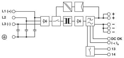
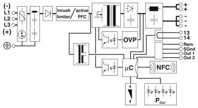
Application Diagrams
QUINT-PS/3AC Industrial Power Supply Block Diagram
QUINT4-PS/3AC/24DC Industrial Power Supply Block Diagram
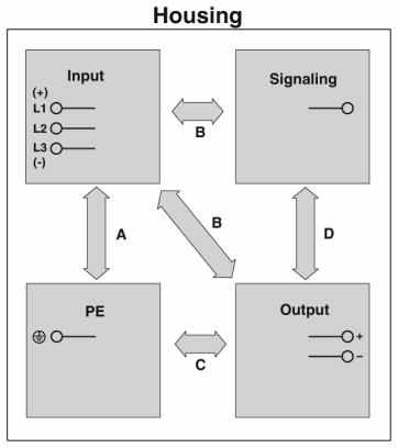
Schematic diagram
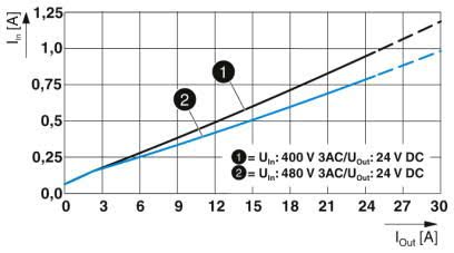
QUINT4-PS/3AC/24DC/10 Input current vs output current
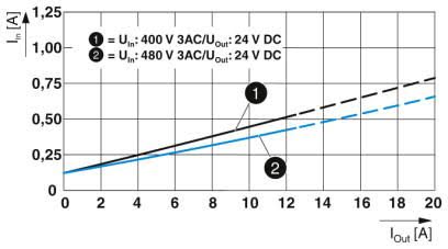
QUINT4-PS/3AC/24DC/20 Input current vs output current
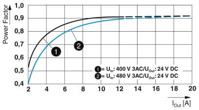
QUINT4-PS/3AC/24DC/10 Power factor diagram
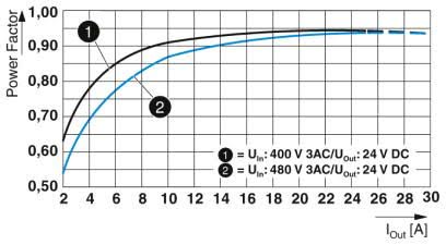
QUINT4-PS/3AC/24DC/20 Power factor diagram
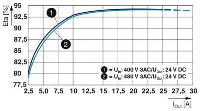
QUINT4-PS/3AC/24DC/10 Efficiency diagram
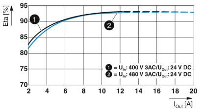
QUINT4-PS/3AC/24DC/20 Efficiency diagram
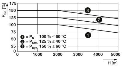
QUINT4-PS/3AC/24DC/10 Output power depending on the installation height
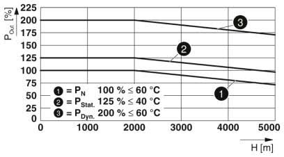
QUINT4-PS/3AC/24DC/20 Output power depending on the installation height
Click on a part number for ordering information
Product Image
Product Description
Part No.
QUINT4-PS/3AC/24DC/10 Power Supply - QUINT power supply with free choice of output characteristic curve, SFB (selective fuse breaking) technology, and NFC interface, input: 3-phase, output: 24 V DC/10 A
QUINT4-PS/3AC/24DC/20 Power Supply - QUINT power supply with free choice of output characteristic curve, SFB (selective fuse breaking) technology, and NFC interface, input: 3-phase, output: 24 V DC/20 A
QUINT-PS/3AC/24DC/40 Power Supply - QUINT power supply for DIN rail mounting with SFB (Selective Fuse Breaking) Technology, input: 3-phase, output: 24 V DC/40 A
QUINT-PS/3AC/48DC/20 Power Supply - QUINT power supply for DIN rail mounting with SFB (Selective Fuse Breaking) Technology, input: 3-phase, output: 48 V DC/20 A
