|
QOS (Quality of Service)
|
- Bandwidth Allocation via rate limiting
- IEEE 802.1P tagged frame priority control
- IEEE 802.1P priority tag remapping
- IP TOS (Type of Service) priority for IPV4 Diffserv or IPV6 traffic class frames
- Congestion Service Policy through WQF (Weighted Fair Queuing) or Strict Priority Queuing (default)
|
|
VLAN Tagging
|
- Default – Transparent to VLAN frames
- Enable discarding of tagged frames
- Enable discarding of untagged frames
- Untag – Removes any existing tag
- Insert Tag – Insert (if original frame is untagged) or replace (if original frame is tagged) the VLAN ID and priority with the configured default VLAN ID and priority tag.
- Insert Double tag (Q in Q) – Append an additional tag using the configured default VLAN ID and priority.
|
|
Unknown Multicast Frame filtering
|
When enabled, Multicast frames with an unknown destination address are not allowed to egress the port
|
|
Unknown Unicast Frame filtering
|
When enabled, Unicast frames with an unknown destination address are not allowed to egress the port
|
|
Unidirectional Ethernet
|
When enabled, provides the ability to restrict port to one-way traffic flow. Used in applications such as unidirectional video broadcasting as well as providing security for ethernet connections in accessible public areas
|
|
Configuration Mode selection
|
Select whether the module is to use the on-board DIP switches or enable the management module in the chassis to manage
|
|
Auto-MDIX
|
Can manually set Auto or MDIX on the copper port via on-board strap or via the management card.
Auto-MDIX (automatic medium-dependant interface crossover) detects the signaling on the UTP interface to determine the type of cable connected (straight-through or crossover) and automatically configures the connection when enabled. With Auto-MDIX enabled, either a straight-through or crossover type cable can be used to connect the media converter to the device on the other end of the cable.
|
|
Module Information
|
- Chassis slot number that the module is in
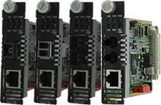
- Media converter model and serial number
- User configurable media converter module name
- User configurable fiber port name
- User configurable copper port name
- Hardware revision number
- Firmware version number
|
|
Module DIP switch settings
|
View hardware DIP switch settings
|
|
Selectable Max Packet Size
|
Set max packet size to 1522, 1518 or 2048 (default)
|
|
10BaseT Extended Distance
|
Normal/extended – default Normal. By configuring as “extended”, the 10baseT receiver sensitivity is increased providing the possibility of an 10BaseT connection greater than 100m.
|
|
Port Control
|
Enable or disable individual fiber or copper port on the module
|
|
Copper Port Status
|
- Port Enabled (Yes/No)
- Link Status (Up/Down)
- Auto Negotiation Settings (Disabled, Complete or In Progress)
- Resolved as crossover MDI or MDIX type
|
|
Fiber Port Status
|
- Port Enabled (Yes/No)
- Connector type (SC, LC, ST)
- Link Status (Up/Down)
- Far End Fault (OK, Failed)
- Fiber Loopback mode (On/Off)
|
|
Module Control
|
- Reset card
- Reset to factory default
- Reset Statistical counters
- Phy specific commands such write/read config, read dip switches
- Update firmware
- Fiber Loopback mode. (On/Off)
- Upload/download configuration
|
|
Backup and Restore
|
Provides fast and easy module replacement. Management module will always save a copy of the media converter configuration and will restore this configuration automatically to the media module when it is detected in the slot
|
|
Detailed port statistics
|
To assist in troubleshooting copper and fiber links, an extensive list of ingress and egress counters for both copper and fiber ports are available. These statistics can be viewed locally via the management module or from a central SNMP NMS on the network
|
|
Auto-Negotiation (802.3u)
|
The media converter supports auto negotiation on the 10/100Base-TX interface.
|
|
Link Pass-Through
|
With Link Pass-Through the state of the UTP receiver is passed to the fiber transmitter to make the media converter appear transparent to the end devices that are connected. In addition if Far-End Fault is enabled the media converter can turn off the 10/100Base-TX transmitter when a FAR-End Fault is received. Using Link Pass-Through with Far-End Fault minimizes data loss when a fault occurs. Should a fault occur, the end devices have the indication of a failure available to them making trouble shooting easier.
|
|
Far-End Fault (FEF)
|
The media converter implements the 802.3 standard for Far-End Fault for the indication and detection of remote fault conditions on the 100Base-X fiber connection. With Far-End Fault enabled the media converter transmits the Far-End Fault Indication over the 100Base-X fiber connection whenever a receive failure is detected on the 100Base-X fiber connection. The media converter continuously monitors the 100Base-X fiber connection for a valid signal. The action the media converter takes on receiving a Far-End Fault Indication is dependent on the Link Pass-Through switch setting.
|
|
Pause (IEEE 802.3xy)
|
Pause signaling is an IEEE feature that temporarily suspends data transmission between two devices in the event that one of the devices becomes overwhelmed. The media converter supports pause negotiation on the 10/100Base-TX copper connection.
|
|
Remote Loopback
|
The media converter is capable of performing a loopback on the fiber port.
|