

Live Chat Now
→
Send an Email
→
Call Us
→
Error!
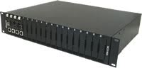
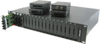
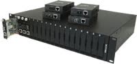
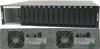
The Perle MCR1900 Media Converter Chassis is the most reliable high density modular chassis system available today. It is ideal for enterprise and campus environments where multiple points of copper and/or fiber integration are essential. An end-to-end copper to copper, copper to fiber, multimode to single mode or multimode to multimode solution can be achieved by pairing modules in this high density chassis with another Perle MCR1900 chassis standalone media converters, or standalone Ethernet extenders. Management of Media Converter Modules and chassis can be performed with the addition of a chassis management module. For a low to mid density solution, please check out the MCR200 Media Converter Chassis.
For those environments requiring a medium to large-scale deployment of media converters, a centralized platform that simplifies the configuration, administration, monitoring, and troubleshooting of this gear is recommended. PerleVIEW Device Management software is a multi-user, Windows server-based application that delivers this level of Enterprise-grade solution.
| High Density Media Converter Platform | Insert up to 19 modules into a single 2U chassis. The modules share a common power source. |
| Rugged Chassis Design |
|
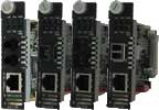
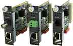
| Hot-Swappable modules | Modules can be inserted and removed with no impact to the rest of the system. Upon insertion the module will automatically be powered up and begin functioning. Modules can be placed in any slot and in any order. |
| Power Supply Failover | On dual power supply configurations, the load sharing power supplies provide instant failover should a power supply or power source fail. A single power supply can provide more than sufficient power for a fully loaded system. |
| Intelligent Alarm Relay | A backplane controller provides continuous monitoring of vital chassis resources. The built-in, normally open/closed, dry contact relay will engage on the following fault conditions:
|
Specifications
HTSUS Number:
8517.62.0020
UNSPSC Code:
43201602
ECCN:
5A991


Features
Intelligent Alarm Relay
Hot-swappable Modules
All modules, management module and power supplies are hot-swappable
Power
Nominal input voltage
115/230 VAC
115/230 VAC
24/48v DC
24/48v DC
Input Voltage Range
90 - 264 VAC
90 - 264 VAC
18 - 72v DC
18 - 72v DC
Capacity
120 watts max.
240 watts max.
The dual supply provides redundancy for instant fail-over. Power supplies load share
120 watts max.
240 watts max.
The dual supply provides redundancy for instant fail-over. Power supplies load share
AC input frequency
47 - 63 Hz
47 - 63 Hz
N/A
N/A
International Power Line Cords by Model
N/A
N/A
LEDs
Power Supply A Status
Power Supply A and B status
Power Supply A Status
Power Supply A and B status
Grounding
Dual ground screws for #10 ring terminals or grounding lug connectors provide a reliable chassis ground connection.
Environmental Specifications
Heat Output (BTU/HR)
17
29
19 at 24vdc, 25 at 48vdc
34 at 24vdc, 49 at 48vdc
MTBF (Hours)*
31,716 Hours
255,530 Hours
32,051 Hours
255,531 Hours
Operating Temperature
0°C to 50°C (32°F to 122°F)
Storage Temperature
-25°C to 70°C (-13°F to 158°F)
Humidity
5 to 95% (non-condensing) for both storage and operation.
Case
SECC Zinc plated sheet metal (1 mm)
Ingress Protection Rating
IP30 with all slots occupied
Altitude
up to 3,038 meters (10,000 ft)
Mounting
2U - 19' rack mounting hardware is included
2U - 23' Telcom / ETSI rack mounting hardware is optional
Product Weight and Dimensions
Weight
6.32 kg, 14 lbs
7.0 kg, 15.4 lbs
6.39 Kg, 14.1 lbs
7.14 kg, 15.74 lbs
Dimensions
356 x 435 x 89 mm, 14 x 17.2 x 3.5 in
Packaging
Shipping Weight
7.76 kg, 17 lbs
9.0 kg, 19.8 lbs
7.76 kg, 17.11 lbs
9.0 kg, 19.8 lbs
Shipping Dimensions
559 x 482 x 178 mm, 22 x 19 x 7 in
Regulatory Approvals
Emissions
Immunity
Safety
*Calculation model based on MIL-HDBK-217-FN2 @ 30°C
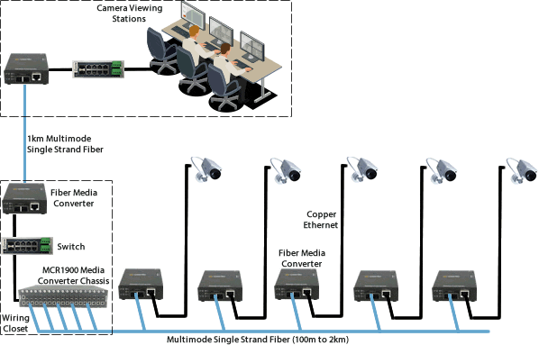
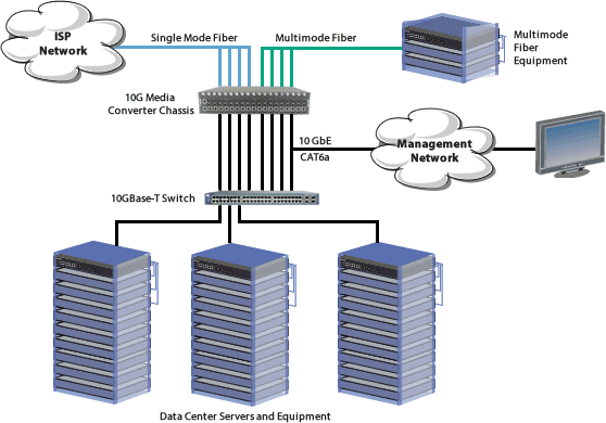
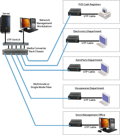
Ethernet to Fiber in a Campus Network
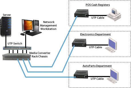
The use of chassis-based media converters is a cost effective means in providing fiber connectivity in a campus network. By consolidating Ethernet to fiber conversion in a rack mount media converter chassis, various types of fiber links can be brought into a single wiring closet platform. This simplifies deployment and maintenance and also provides a scalable means to grow your network as needed.
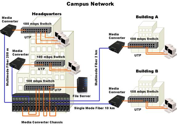
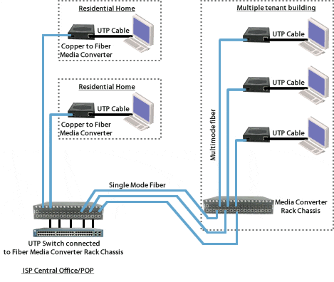
High Density Fiber Distribution from UTP Switch Equipment at Corporate Headquarters
In this enterprise campus application, up to 19 Perle Ethernet to Fiber Media Converters are installed in the MCR1900 Media Converter Chassis. A remote fiber enabled Ethernet switch is connected directly to the central MCR1900 Chassis. A standalone Media Converter converts the fiber to Ethernet in a fiber-to-desktop application. Another standalone Fiber Media Converter is connected to a remote office Ethernet switch. In all cases, multimode or single-mode fiber can be used. Fiber links can be extended up to 120km using single-mode fiber.
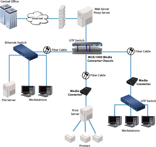
Enterprise Infrastructure
Enterprise Infrastructure using Fiber Optics
Create a fiber infrastructure for your enterprise network without any wholesale replacement of existing copper-based equipment.
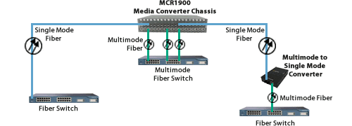
High Density Fiber Distribution from Fiber Switch Equipment at Corporate Headquarters
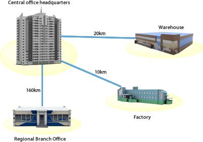
In this enterprise campus application, up to 19 Perle Fiber to Fiber Media Converters ( Multimode to Single mode ) are installed in the MCR1900 Media Converter Chassis. A remote single mode fiber enabled Ethernet switch is connected directly to the central MCR1900 Chassis. Another standalone Fiber Media Converter is connected to a remote office Fiber switch. In all cases, multimode or single-mode fiber can be used. Fiber links can be extended up to 160km using single-mode fiber.
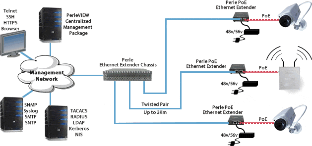
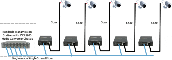
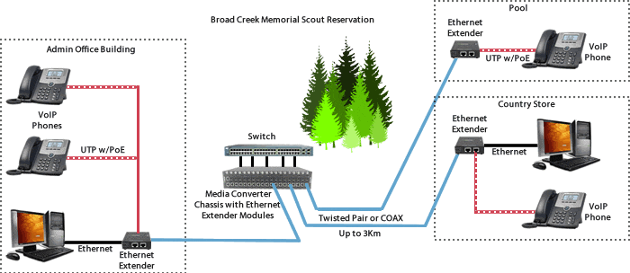
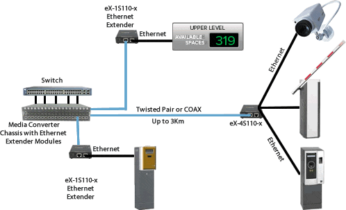
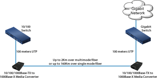
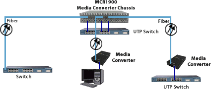
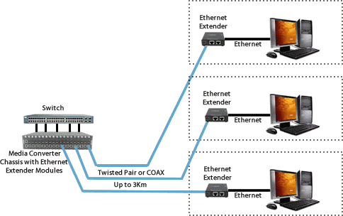
Extend 10/100/1000 Ethernet across Twisted Pair or Coaxial Wire
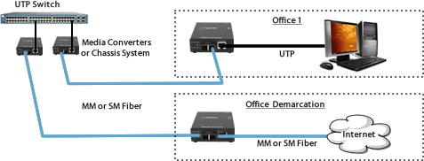
Extend an Ethernet link beyond the 100 meter ( 328 feet ) limit using Ethernet Extenders. Distances of up to 3 km ( 10,000 feet ) can be achieved over twisted pair Cat 5,6 or 7 cable. You can also install along with Ethernet to Fiber Media Converter Modules and extend the Ethernet connection over fiber for greater distance.
Click on a part number for ordering information
Product Image
Product Description
Part No.
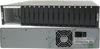
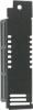
MCR1900-AC - 19 Slot Chassis for Media Converter and Ethernet Extender Modules. Single AC power expandable to dual AC power. 15 empty slot cover plates included
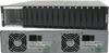
MCR1900-DAC - 19 Slot Chassis for Media Converter and Ethernet Extender Modules. Dual AC power. 15 empty slot cover plates included
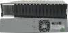
MCR1900-DC - 19 Slot Chassis for Media Converter and Ethernet Extender Modules. Single 48vDC power expandable to dual DC power. 15 slot plates included
MCR1900-DDC - 19 Slot Chassis for Media Converter and Ethernet Extender Modules. Dual 48vDC power. 15 slot plates included
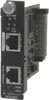
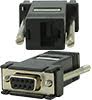
MCR-MGT - Management Module for the MCR chassis. 10/100/1000 ethernet RJ45, serial console port RJ45, SNMP read/write, Telnet/SSH and Internet Browser access and advanced security
Related Accessories
