CM-10G Managed Media Converter Modules
10 Gigabit Copper and Fiber Converters

- Fiber to Fiber, copper to fiber and copper to copper conversion
- 2 empty slots that use 10G transceivers supplied by Perle, Cisco or other MSA compliant SFP+ and XFPs
- Advanced features –Smart Link Pass-Through, Fiber Fault Alert, Built-in Link Test Generator and Loopback
- High density applications with Perle MCR1900 Media Converter Chassis
- Manage via SNMP, CLI - Telnet/SSH, Internet browser, or PerleVIEW Centralized Management Package with an MCR-MGT Media Converter Management Module
- Support for Power Level 1,2,3 as well as high-power Level 4 XFPs
- Optical signal regeneration: 3R (re-amplify, reshape, and retime)
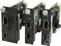
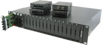
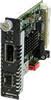
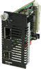
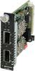
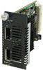
Installed in a high density MCR1900 Media Converter Chassis, Perle CM-10G Managed Media Converter Modules transparently connect 10 Gigabit Ethernet links over multimode or single mode fiber. Each 10GbE Media Converter comes with two pluggable transceiver ports that support fiber to fiber, copper to fiber or copper to copper media conversion. These media converters can be used in an unmanaged environment or can be SNMP manageable to enable complete control and status viewing of your fiber links. 10G Media Converter Modules are also available for unmanaged networks, or for low to mid-density application check out the stand alone SMI-10G Managed Media Converter.
Fiber to Fiber and Copper to Fiber conversion is achieved by inserting XFP or SFP+ fiber transceivers that support multimode and single-mode fiber, including CWDM/DWDM wavelengths. Copper to copper is achieved by inserting SFP+ Direct Attach Cable (DAC), also known as twinax, or XFP 10Gbase-CX4 transceivers.
The empty transceiver ports on the CM-10G Managed Media Converter Modules allow for flexible network configurations to meet any requirement using a variety of 10G transceivers supplied by Perle, Cisco or other manufacturers of MSA compliant SFP+ and XFPs. You can use these products to convert:
- XFP to XFP
- XFP to SFP+
- SFP+ to CX4
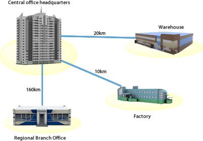
Perle 10 Gigabit Ethernet to Fiber Converters provide an economical path to extend the distance of an existing 10GbE link. Network Administrators can “see-everything” with Perle’s advanced features such as Smart Link Pass-Through, Fiber Fault Alert, a built-in Link Test capability and Loopback. Along with a Media Converter Management Module in the chassis, configuration and monitoring of the copper and fiber ports can be performed. This allows for more efficient troubleshooting and less on-site maintenance. These cost and time saving features, along with a lifetime warranty and free worldwide technical support, make CM-10G Managed Media Converter Modules the smart choice for IT professionals.
For those environments requiring a medium to large-scale deployment of media converters, a centralized platform that simplifies the configuration, administration, monitoring, and troubleshooting of Perle Managed Media Converters is recommended. PerleVIEW Device Management software is a multi-user, Windows server-based application that delivers this level of Enterprise-grade solution.
CM-10G Managed Media Converter Features
SFP Speed Sensing | Automatically detects whether a SFP has been inserted and adjusts the speed accordingly |
Smart Link Pass-Through |
When the Smart Link Pass-Through switch is enabled (default), each port will reflect the state of its port peer. In this mode, if a link loss is detected on one port, the transmit signal on the other port is disabled “passing through” the state of the failed link. This enables managed switches and other devices to report link failures to their network NMS. When the switch is in the down position, Smart Link Pass-Through is disabled. If a link loss is detected on one port, the transmit signal remains enabled on the other port. |
Fiber Fault Alert | With Fiber Fault Alert the state of the 10 Gigabit Ethernet receiver is passed to the transmitter. This provides fault notification to the partner device attached to the 10G Ethernet interface of the media converter. |
3R – Optical Signal Regeneration | Optical signal regeneration: 3R ( Re-amplify, Reshape, and Retime the signal ) ensures that there is a quality link at 10 Gigabit speeds. |
Built-in Link Test | When enabled, the built-in packet generator transmits Ethernet test frames to its 10 Gigabit Ethernet peer. The remote media converter will auto-detect the test frames and loopback the test frames. Any frames received in error, will cause the Power, LK1 and LK2 LEDs to illuminate in a specific combination to identify the error. During the test different bit test patterns will be utilized every 5 seconds ensuring a thorough link test. |
Test Mode Auto-detect | When enabled through the management interface, the remote media converter will enter test mode automatically when requested by its central site peer. This virtually eliminates unnecessary truck rolls to a remote site when diagnosing a link failure. |
EDC Mode Control | Electronic Dispersion Compensation (EDC) is an algorithmic method used to compensate for optical dispersion that occurs on high speed 10 Gigabit links. EDC mode settings are automatically configured by the media converter based on the information retrieved from the SFP+ or XFP module. This will enable proper operation for extended multimode 10GBase-LRM as well as active or passive copper cabling. |
Module Temperature Protection | Protects your DOM/DMI capable SFP+ or XFP module by monitoring its internal temperature and will automatically shut down the XFP or SFP if the module is operating above its maximum temperature threshold. |
High Power Level 4 XFPs | High powered Level 4 XFPs are supported in XTSH and XTXH models. |
Gigabit SFP support | The 10 Gigabit media converter model with dual SFP+ slots can also support Gigabit (1000Base-X) SFPs. This allows users to use Gigabit SFPs today and migrate to 10G SFP+ in the future. Both slots must be populated with Gigabit SFPs. |
Jumbo Packets | Transparent to Jumbo Frames with a maximum MTU size of 10,024 bytes |
VLAN | Transparent to VLAN tagged packets. |
Remote Loopback | Capable of performing a loopback on each 10 Gigabit interface. In this mode, all frames received on the port in loopback mode will be transmitted back. This provides users with the capability of utilizing their own in-house test generators for testing the link. |
Additional features available when installed along with a Media Converter Management Module in a Perle MCR1900 Media Converter Chassis
Configuration Mode selection | Select whether the module is to use the on-board DIP switches or enable the management module in the chassis to manage. |
Module Information |
|
Module DIP switch settings | View hardware DIP switch settings. |
Port Control | Enable or disable individual fiber ports on the module. |
Fiber Port Status |
|
Module Control |
|
Backup and Restore | Provides fast and easy module replacement. Management module will always save a copy of the media converter configuration and will restore this configuration automatically to the media module when it is detected in the slot. |
Manage Tune-able DWDM XFP modules | Select transceiver ITU 50GHz center wavelengths and channel numbering on tune-able XFP transceivers. |
Hardware Specifications
Power | Dual XFP | XFP to SFP |
---|---|---|
Maximum Power Consumption (watts) | XTX: 12.0 * XTXH: 16.3 * |
XTS: 9.1 * XTSH: 16.3 * |
Total Transceiver Power Supported (watts) | XTX: 7.0 XTXH: 11.0 |
XTS: 5.0 XTSH: 7.0 |
Indicators | ||
Power / TST |
|
|
LK1, LK2 |
|
|
Switches | ||
Smart Link Pass-Through | When the Smart Link Pass-Through switch is enabled (default), each port will reflect the state of its port peer. In this mode, if a link loss is detected on one port, the transmit signal on the other port is disabled “passing through” the state of the failed link. This enables managed switches and other devices to report link failures to their network NMS.
When the switch is in the down position, Smart Link Pass-Through is disabled. If a link loss is detected on one port, the transmit signal remains enabled on the other port. |
|
Fiber Fault Alert | Enabled (Default - Up) With Fiber Fault Alert the state of the 10 Gigabit ethernet receiver is passed to the transmitter. This provides fault notification to the partner device attached to the 10G ethernet interface of the media converter Disabled (Down) |
|
EDC Mode | Electronic Dispersion Compensation (EDC) is an algorithmic method used to compensate for optical dispersion that occurs on high speed 10 Gigabit links. EDC mode settings are automatically configured by the media converter based on the information retrieved from the SFP+ or XFP module. This will enable proper operation for extended multimode 10GBase-LRM as well as active or passive copper cabling.
In the default UP switch position the media converter will automatically set the 10G transceiver to match the EDC type declared by the SFP+ / XFP module to either to “linear” or “limiting”. In the event that there is a mismatch, setting the switch to the Down position on the media converter will flip the setting to that declared by the module. |
|
Loopback | Capable of performing a loopback on each 10 Gigabit interface. In this mode, all frames received on the port in loopback mode will be transmitted back. This provides users with the capability of utilizing their own in-house test generators for testing the link. | |
Connectors | Dual XFP | XFP to SFP |
Pluggable 10G Fiber Transceiver slots (Hot insertion and removable) | Two 10 Gigabit XFP Slots
|
One 10 Gigabit SFP+
|
Voltages supplied to XFP slots | 1.8V, 3.3V, 5V and -5.2V | 1.8V, 3.3V, 5V and -5.2V |
Supported 10 Gigabit Fiber pluggable transceivers | IEEE 802.3ae compliant:
|
IEEE 802.3ae compliant:
|
Supported 10 Gigabit Copper pluggable transceivers | IEEE 802.3ak compliant:
|
SFP+ Direct Attach Cable (DAC). Also known as:
IEEE 802.3ak compliant:
|
Chassis Slot profile | XTX: one slot
XTXH: two slots |
XTS: one slot
XTSH: two slots |
Environmental Specifications | Dual XFP | XFP to SFP |
Operating Temperature | 0° C to 50° C (32° F to 122° F) | |
Storage Temperature | minimum range of -25° C to 70° C (-13° F to 158° F) | |
Operating Humidity | 5% to 90% non-condensing | |
Storage Humidity | 5% to 95% non-condensing | |
Operating Altitude | Up to 3,048 meters (10,000 feet) | |
Heat Output (BTU/HR) |
XTX: 39.2
XTXH: 55.6 |
XTS: 31.0
XTSH: 55.6 |
MTBF (Hours) Calculation model based on MIL-HDBK-217-FN2 @ 30 °C |
335,191 | 335,191 |
Packaging | ||
Shipping Weight | 0.25 Kg, 0.55 lbs | |
Shipping Dimensions | Standard Power Models: 150 x 210 x 40 mm, 5.9 x 8.3 x 1.6 inches
High Power models (XTXH, XTSH): 170 x 260 x 70 mm, 6.7 x 10.2 x 2.8 inches |
|
Regulatory Approvals | ||
Emissions | FCC Part 15 Class A, EN55022 Class A | |
CISPR 22 Class A CISPR 32:2015/EN 55032:2015 (Class A) CISPR 24:2010/EN 55024:2010 |
||
EN61000-3-2 | ||
Immunity | EN55024 | |
Safety | UL/EN/IEC 62368-1 CAN/CSA C22.2 No. 62368-1 |
|
UL 60950-1 IEC 60950-1(ed 2); am1, am2 EN 60950-1:2006+A11:2009+A1:2010+A12:2011+A2:2013 |
||
CE | ||
Environmental | Reach, RoHS and WEEE Compliant | |
Other | ECCN: 5A991 | |
HTSUS Number: 8517.62.0020 | ||
Perle Limited Lifetime Warranty |
*Maximum rating for both media converter and modules inserted. Actual rating is dependent on the power consumption of the SFP+/XFP modules inserted.
High Density Fiber Distribution from Fiber Switch Equipment at Corporate Headquarters |
---|
In this enterprise campus application, up to 18 Perle Managed Media Converters are installed in the MCR1900 Media Converter Chassis. The 19th slot in the chassis is filled the MCR-MGT Management Module. All media converts in the chassis are managed by SNMP, Telnet or an internet browser interface. A remote fiber enabled Ethernet switch is connected directly to the central MCR1900 Chassis. Another Fiber Media Converter is connected to a remote office switch. In all cases, multimode or single-mode fiber can be used. Fiber links can be extended up to 160km using single-mode fiber. ![]() |
Ethernet to Fiber in a Campus Network |
The use of chassis-based media converters is a cost effective means in providing fiber connectivity in a campus network. By consolidating Ethernet to fiber conversion in a rack mount media converter chassis, various types of fiber links can be brought into a single wiring closet platform. mThis simplifies deployment and maintenance and also provides a scalable means to grow your network as needed. ![]() |
Managed Ethernet over Fiber Links |
Manage your multimode to single mode or multimode to multimode link with an MCR200 chassis housing a media converter and management module. Ideal for use in managed networks with low density fiber applications, this Managed Media Converter is connected across a fiber link to a remote media converter. The copper or fiber link on the managed standalone unit can provide vital information and status to network management tools such as SNMP. ![]() |
10 Gigabit Ethernet Fiber Repeater |
Extend the network distance of 10 Gigabit Fiber Links ![]() |
10 Gigabit Ethernet Fiber Extender |
Extend the network distance between two 10 Gigabit Fiber Switches ![]() |
10 Gigabit Copper to Fiber Media Conversion |
Convert one 10G Ethernet media to another ![]() ![]() |
10 Gigabit Datacenter Fiber Upgrade |
Replace old CX4 switch with a new fiber switch ![]() |
CWDM Transponder |
Connect XFP to SFP+ and SFP+ to SFP+ Media Converters to Fiber Mux ![]() |
DWDM Transponder |
Set wavelength on tune-able XFP DWDMs via media converter management ![]() |
Click on 'Model Name' to see part numbers
Model | Port | Slot | SFP+ Power Levels | XFP Power Levels | Maximum Total Transceiver Power Supported |
---|---|---|---|---|---|
CM-10G-XTS | Port 1 | XFP | - | Level 1 ( up to 1.0 watts ) | 5.0 watts |
- | Level 2 ( 1.5 to 2.5 watts ) | ||||
- | Level 3 ( 2.5 to 3.5 watts ) | ||||
Port 2 | SFP+ | Level 1 ( up to 1.0 watts ) | - | ||
Level 2 ( up to 1.5 watts ) | - | ||||
CM-10G-XTSH | Port 1 | XFP | - | Level 1 ( up to 1.0 watts ) | 7.0 watts |
- | Level 2 ( 1.5 to 2.5 watts ) | ||||
- | Level 3 ( 2.5 to 3.5 watts ) | ||||
- | Level 4 ( 3.5 to 5.5 watts ) | ||||
Port 2 | SFP+ | Level 1 ( up to 1.0 watts ) | - | ||
Level 2 ( up to 1.5 watts ) | - | ||||
CM-10G-XTX | Port 1 | XFP | - | Level 1 ( up to 1.0 watts ) | 7.0 watts |
- | Level 2 ( 1.5 to 2.5 watts ) | ||||
- | Level 3 ( 2.5 to 3.5 watts ) | ||||
Port 2 | XFP | - | Level 1 ( up to 1.0 watts ) | ||
- | Level 2 ( 1.5 to 2.5 watts ) | ||||
- | Level 3 ( 2.5 to 3.5 watts ) | ||||
CM-10G-XTXH | Port 1 | XFP | - | Level 1 ( up to 1.0 watts ) | 11.0 watts |
- | Level 2 ( 1.5 to 2.5 watts ) | ||||
- | Level 3 ( 2.5 to 3.5 watts ) | ||||
- | Level 4 ( 3.5 to 5.5 watts ) | ||||
Port 2 | XFP | - | Level 1 ( up to 1.0 watts ) | ||
- | Level 2 ( 1.5 to 2.5 watts ) | ||||
- | Level 3 ( 2.5 to 3.5 watts ) | ||||
- | Level 4 ( 3.5 to 5.5 watts ) |